FRENCH ENGLISH PROPANE FORCED-AIR HEATERS INSTRUCTIONS FOR USE SPANISH IMPORTANT Read this manual carefully before assembling, using or servicing this heater. Keep this manual for future reference. If you have questions about assembly, operation, servicing or repair of this heater, please call Coleman at 1-800-835-3278 or TDD: 316-832-8707. In Canada call 1 800 387-6161.
GENERAL SAFETY INFORMATION This manual contains important information about the assembly, operation and maintenance of this construction heater. General safety information is presented in these first few pages and is also located throughout the manual. Particular attention should be paid to information accompanied by the safety alert symbol “ WARNING”. Keep this manual for future reference and to educate new users of this product. This manual should be read in conjunction with the labeling on the product.
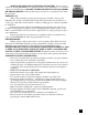
MAKE SURE ADEQUATE VENTILATION IS PROVIDED. Provide a fresh outside air opening at least three (3) square feet (0.3 m2) or its equivalent, i.e., 1' x 3' (0.3 m x 0.9 m) for each heating unit. DO NOT USE THIS HEATER IN LIVING QUARTERS OR WHILE SLEEPING! California lists carbon monoxide as a reproductive toxin under Proposition 65. GENERAL SAFETY INFORMATION Continued ENGLISH PROPANE GAS: This product is fueled by propane gas. Propane gas is invisible, odorless, and flammable.
CONTENTS SECTION PAGE General Safety Information . . . . . . . . . . . . . . . . . . . . . . . . 2,3 Product Identification . . . . . . . . . . . . . . . . . . . . . . . . . . . . 4 Unpacking . . . . . . . . . . . . . . . . . . . . . . . . . . . . . . . . . . . . . . 5 Theory of Operation . . . . . . . . . . . . . . . . . . . . . . . . . . . . . . 5 Propane Supply . . . . . . . . . . . . . . . . . . . . . . . . . . . . . . . . . . 5, 6 Ventilation . . . . . . . . . . . . . . . . . . . . . . . . . . . . .
UNPACKING The Fuel System: The hose/regulator assembly attaches to the propane gas supply. The propane gas moves through the thermoelectric valve and out the nozzle. The Air System: The motor turns the fan. The fan pushes air into and around the combustion chamber. This air is heated and provides a stream of clean, hot air. The Ignition System: The piezo spark ignitor (Model 5070A) or Electronic Module (Model 5075A) sends voltage to the electrode. The spark at the electrode ignites the fuel air mixture.
PROPANE SUPPLY Continued The chart below shows the minimum number of 20-pound or larger tanks needed to run these heaters at the temperature indicated for at least 10 hours. Do not operate them with tanks smaller than indicated. Reduced performance will result. NUMBER OF TANKS REQUIRED Average Temperature (°F) At Tank Location 5070A751 (40,000 BTU/Hr.) 5075A751 (80,000 BTU/Hr.
PREPARATION Continued ENGLISH 3. Connect POL fitting on hose/regulator assembly to propane tank(s). Turn POL fitting counterclockwise into threads on tank. Tighten firmly. IMPORTANT: Tighten regulator with vent pointing down. Pointing vent down protects regulator from weather damage. Regulator With Vent Pointing Down 4. Open valve on propane tank(s) slowly. Note: If not opened slowly, excess-flow check valve on propane tank will stop gas flow. If this happens, close propane valve and open again slowly.
OPERATION Continued 4. Plug power cord of heater into a three-prong, grounded extension cord. Extension cord must be at least six feet long. Extension cord must be UL listed. Extension Cord Size Requirement Up to 50 feet (15 m) long, use 18 AWG rated cord. 51 to 100 feet (30 m) long, use 16 AWG rated cord. 101 to 200 (61 m) feet long, use 14 AWG rated cord. 5. Plug extension cord into a 120 volt/60 hertz, three-hole, grounded outlet. The motor will start, turning the fan forcing air through the heater. 6.
To Stop Heater OPERATION Continued ENGLISH 1. Tightly close valve on propane tank(s). 2. Wait a few seconds. Heater will burn gas left in hose. 3. Unplug heater. WARNING STORAGE Disconnect heater from propane supply tank(s) before storage. 1. Store propane tank(s) in safe manner. See Chapter 5 of Standard for Storage and Handling of Liquefied Petroleum Gases, ANSI/NFPA 58. Follow all local codes. 2.
MAINTENANCE Continued 6. FAN - Clean every 500 hours of operation or as needed. A. Remove screws along each side of heater and on top of the motor guard using a Phillips screwdriver. These screws attach top and lower shells together. B. Lift top shell off. C. Lift out motor/guard assembly. IMPORTANT: Do not allow the motor/guard assembly to rest on the fan or damage may be caused to the blades. D. Clean fan using soft cloth moistened with kerosene or solvent. Dry fan thoroughly.
Never attempt to service heater while it is plugged in, connected to propane supply, operating or hot. Severe burns and electrical shock can occur. SYMPTOM POSSIBLE CAUSE REMEDY Fan does not turn when heater is plugged in. No electrical power to heater Check voltage to electrical outlet. If voltage is good, check heater power cord for breaks. Fan blades bent Replace fan. See Replacing Fan, Page 13. Defective motor Replace motor. See Replacing Motor, page 12.
SERVICE PROCEDURES WARNING Never attempt to service heater while it is plugged in, connected to propane supply, operating, or hot. Severe burns and electrical shock can occur. REPLACING MOTOR 1. Remove top shell (see FAN under maintenance). 2. Lift out motor/guard assembly. 3. Use a 1/8" hex wrench to loosen setscrew which holds fan to motor shaft. 4. Remove fan from motor shaft (it may be necessary to pry the fan from the shaft) being careful not to damage the blades. 5.
REPLACING FAN 1. Remove motor/guard assembly (follow steps 1 through 4 above). 2. File the setscrew mark off the motor shaft. 3. Replace fan (follow steps 9 through 13 above). SERVICE PROCEDURES Continued ENGLISH REPLACING ELECTRODE 1. Remove shell and motor/guard assembly (see FAN under maintenance). 2. Pull wire off of electrode. 3. Remove screw holding electrode to diffuser. 4. Remove electrode from diffuser. 5. Place new electrode in diffuser. 6. Install screw, insure electrode gap is .20 (0.
WIRING DIAGRAM THERMAL SAFETY SWITCH THERMAL SAFETY SWITCH T.E. VALVE T.E. VALVE PIEZO IGNITOR MOTOR BLACK WHITE GREEN MODEL 5075A MODEL 5070A REPLACEMENT PARTS WARNING Use only original replacement parts. Do not substitute or use generic parts. Improper replacement parts could cause serious or fatal injuries. I.D. NO. PART NO.
FRENCH CHAUFFERETTES À AIR PULSÉ, AU GAZ PROPANE MODE D’EMPLOI IMPORTANT Lisez attentivement ce manuel avant d’assembler, d’utiliser ou de réparer la chaufferette ; gardez-le pour le consulter au besoin. Pour toutes questions concernant l’assemblage, le fonctionnement, l’entretien ou la réparation, veuillez composer le 1 800 835-3278 ou le 316-832-8707 aux États-Unis, ou bien le 1 800 387-6161 au Canada.
GÉNÉRALITÉS DE SÉCURITÉ Ce manuel renferme des renseignements importants sur l’assemblage, le fonctionnement et l’entretien des chaufferettes de construction. Les généralités de sécurité sont fournies non seulement dans les premières pages, mais aussi ici et là dans le manuel. Prêtez toujours attention quand vous voyez le symbole « AVERTISSEMENT». Gardez ce manuel pour le consulter au besoin et pour apprendre aux nouveaux utilisateurs à l’employer.
ASSUREZ-VOUS QUE L’APPROVISIONNEMENT EN AIR NEUF SOIT GÉNÉRALITÉS SUFFISANT. Une bouche d’air d’au moins 0,3 m2 (3 pi2) ou l’équivalent, soit 0,3 x 0,9 m (1 x DE 3 pi), est requise pour chaque unité. N’UTILISEZ PAS CETTE CHAUFFERETTE DANS SÉCURITÉ LES LOCAUX HABITÉS OU PENDANT LE SOMMEIL! En Californie, d’après la (suite) Proposition 65, l’oxyde de carbone est répertorié comme agent toxique pour la reproduction. FRENCH GAZ PROPANE : Cet appareil brûle le propane – gaz invisible, inodore et inflammable.
TABLE DES MATIÈRES IDENTIFICATION DU PRODUIT SECTION PAGE Généralités de sécurité . . . . . . . . . . . . . . . . . . . . . . . . . . . . . 16, 17 Identification du produit . . . . . . . . . . . . . . . . . . . . . . . . . . . 18 Déballage . . . . . . . . . . . . . . . . . . . . . . . . . . . . . . . . . . . . . . . 19 Théorie du fonctionnement . . . . . . . . . . . . . . . . . . . . . . . . . 19 Alimentation en propane . . . . . . . . . . . . . . . . . . . . . . . . . . . 19, 20 Ventilation . . . . . .
DÉBALLAGE Approvisionnement en carburant : L’ensemble tuyau souple et régulateur se fixe à la bonbonne de propane. Le gaz traverse la soupape thermoélectrique et sort par l’ajutage. Alimentation en air : Le moteur fait tourner l’hélice. L’hélice propulse l’air dans et autour de la chambre de combustion. Cet air est réchauffé et procure un écoulement continu d’air propre et chaud.
ALIMENTATION EN PROPANE (suite) Le tableau ci-dessous montre le nombre minimal de bonbonnes de 20 lb nécessaires pour faire fonctionner la chaufferette à la température indiquée au moins 10 heures. Ne vous servez pas de bonbonnes plus petites, le rendement en serait réduit. NOMBRE DE BONBONNES REQUISES Température moy.
PRÉPARATION (suite) FRENCH 3. Branchez le raccord CL de l’ensemble tuyau-régulateur à la (aux) bonbonne(s). Tournez le raccord en sens antihoraire dans le filetage de la bonbonne. Serrez à fond. IMPORTANT : Serrez le régulateur en orientant le purgeur vers le sol. Orienter le purgeur vers le sol protège le régulateur des dommages découlant des conditions atmosphériques. Régulateur avec purgeur orienté vers le sol 4. Ouvrez le robinet de la (des) bonbonne(s) lentement.
FONCTIONNEMENT (suite) 4. Branchez le cordon de la chaufferette à une rallonge à 3 broches (à mise à la terre), d’au moins 1,8 m (6 pi) de longueur. Le cordon de rallonge doit être homologué ULC. Exigences quant au cordon de rallonge Jusqu’à 15 m (50 pi) de long, utilisez une rallonge numéro 18, calibre américain de fil. De 15 à 30 m (51 à 100 pi), utilisez une rallonge numéro 16, calibre américain de fil. De 30 à 61 m (101 à 200 pi), utilisez une rallonge numéro 14, calibre américain de fil. 5.
1. Fermez le robinet de la (des) bonbonne(s) de propane à fond. FONCTIONNEMENT (suite) FRENCH Arrêt de la chaufferette 2. Attendez un instant (pour que le gaz qui reste dans le tuyau brûle). 3. Débranchez la chaufferette. AVERTISSEMENT RANGEMENT Débranchez la chaufferette de la (des) bonbonne(s) avant de la ranger. 1. Rangez le propane comme il se doit. Consultez le chapitre 5 «Entreposage et manipulation des gaz de pétrole liquéfiés» de la norme ANSI/NFPA 58. Observez tous les codes municipaux. 2.
ENTRETIEN (suite) 6. HÉLICE - Nettoyez-la toutes les 500 heures de fonctionnement ou au besoin. A. Enlevez les vis du carter (côtés et dessus) avec un tournevis à pointe cruciforme (Phillips). Elles fixent le carter du dessus au carter du dessous. B. Levez le carter du dessus. C. Levez l’ensemble moteur et protecteur. IMPORTANT: Veillez à ce que l’ensemble moteur et protecteur ne repose pas contre l’hélice car ceci risquerait d’endommager les pales. D.
Ne tentez pas de réparer une chaufferette reliée à une bonbonne, fonctionnant ou chaude. Brûlures et chocs électriques graves pourraient en résulter. INDICE CAUSE POSSIBLE SOLUTION L’hélice ne tourne pas quand la chaufferette est branchée. Absence de courant électrique à la chaufferette Vérifiez la tension à la prise. Si elle est bonne, assurez-vous que le cordon de la chaufferette ne soit pas coupé. Pales de l’hélice faussées Remplacez l’hélice. Voyez la marche à suivre à la page 27.
MÉTHODES DE DÉPANNAGE AVERTISSEMENT Ne tentez pas de réparer une chaufferette reliée à une bonbonne, fonctionnant ou chaude. Brûlures et chocs électriques graves pourraient en résulter. REMPLACEMENT DU MOTEUR 1. Enlevez le carter du dessus (voyez «HÉLICE» sous «Entretien»). 2. Levez l’ensemble moteur et protecteur. 3. Avec une clé hexagonale (1/8 po), desserrez la vis d’arrêt ancrant l’hélice à l’arbre moteur. 4.
REMPLACEMENT DE L’HÉLICE 1. Enlevez l’ensemble moteur et protecteur (paragraphes de 1 à 4 de la page précédente). 2. Limez la marque ayant été laissée par la vis d’arrêt sur l’arbre moteur. 3. Remplacez l’hélice (paragraphes de 9 à 13 de la page précédente). MÉTHODES DE DÉPANNAGE (suite) FRENCH REMPLACEMENT DE L’ÉLECTRODE 1. Enlevez l’ensemble moteur et protecteur (voyez «HÉLICE» sous «Entretien»). 2. Retirez le fil de l’électrode. 3. Enlevez la vis immobilisant l’électrode au diffuseur. 4.
SCHÉMA DE CÂBLAGE THERMO- THERMOTHERMAL RUPTEUR SAFETY DE SÉCURITÉ SWITCH T.E. VALVE THERMAL RUPTEUR SAFETY DE SÉCURITÉ SWITCH SOUPAPE T.E. SOUPAPE T.E. T.E. VALVE NOIR ALLUMEUR PIEZO PIÉZO IGNITOR MOTEUR MOTOR NOIR BLACK BLANC WHITE ALLUMEUR MOTEUR 115 VOLTS 60 HZ VERT GREEN ÉLECTRODE BLANC MODÈLES 5075A MODÈLE 5070A PIÈCES DE RECHANGE AVERTISSEMENT N’employez que des pièces de rechange authentiques, jamais de pièces de rechange d’autres marques.
CALEFACTOR A GAS PROPANO CON VENTILACIÓN FORZADA INSTRUCCIONES DE USO SPANISH IMPORTANTE Lea cuidadosamente este manual antes de ensamblar, usar o dar servicio al calefactor. Guarde este manual para referencia futura. Si tiene dudas acerca del ensamblaje, funcionamiento, servicio o reparación de esta unidad, sírvase llamar a Coleman al 1-800-835-3278 o a la línea para personas con dificultad auditiva 316-832-8707. En Canadá llame al 1 800 387-6161.
INFORMACIÓN GENERAL SOBRE SEGURIDAD El presente manual contiene información importante relacionada con el ensamblaje, funcionamiento y mantenimiento de este calefactor para construcciones. Estas primeras páginas incluyen información general sobre seguridad, las cuales se repiten en distintas secciones del manual. Debe prestarse especial atención a toda información acompañada por el símbolo de alerta y seguridad “ ADVERTENCIA”.
ASEGÚRESE DE CONTAR CON VENTILACIÓN ADECUADA. Debe haber una abertura INFORMACIÓN para que circule el aire de por lo menos tres (3) pies cuadrados (0.3 m2) o su equivalente, por GENERAL ej., 1' x 3' (0.3 m x 0.9 m) por cada unidad. ¡NO USE ESTE CALEFACTOR EN SOBRE DEPENDENCIAS HABITADAS O MIENTRAS DUERME! El estado de California incluye SEGURIDAD el monóxido de carbono como una toxina reproductiva en la Proposición 65. Continuación SPANISH GAS PROPANO: Este producto funciona con gas propano.
CONTENIDO SECCIÓN PÁGINA Información general sobre seguridad . . . . . . . . . . . . . . . . . . 30, 31 Identificación del producto . . . . . . . . . . . . . . . . . . . . . . . . 32 Desembalaje . . . . . . . . . . . . . . . . . . . . . . . . . . . . . . . . . . . . 33 Teoría de funcionamiento . . . . . . . . . . . . . . . . . . . . . . . . . . 33 Suministro de gas propano . . . . . . . . . . . . . . . . . . . . . . . . . 33, 34 Ventilación . . . . . . . . . . . . . . . . . . . . . . . . . . . . . . . .
DESEMBALAJE Sistema de combustible: El conjunto regulador/manguera se conecta al suministro de gas. El gas propano pasa por la válvula termoeléctrica y sale por la boquilla. Sistema de aire: El motor hace girar el ventilador. El ventilador empuja el aire hacia adentro y a la cámara de combustión. El aire se calienta y suministra un flujo limpio y caliente. Sistema de encendido: El encendedor tipo piezo (Modelo 5070A) o el Módulo Electrónico (Modelo 5075A) envía voltaje al electrodo.
SUMINISTRO DE GAS PROPANO CONTINUACIÓN El cuadro a continuación muestra el mínimo número de tanques de 20 libras, o más grandes, necesarios para hacer funcionar a estos calefactores a la temperatura indicada durante 10 horas como mínimo. No los haga funcionar con tanques de menos libras que las indicadas ya que obtendrá menor rendimiento. NÚMERO DE TANQUES NECESARIOS Temperatura promedio (en °F) donde están los tanques 32° (0°C) 5070A751 (40,000 BTU/h.) 5075A751 (80,000 BTU/h.) 1-20 lb. 1-100 lb.
PREPARACIÓN CONTINUACIÓN SPANISH 3. Conecte el acoplamiento POL del conjunto regulador/manguera al tanque(s) de gas propano. Enrosque el acoplamiento POL en sentido antihorario en el tanque. Ajuste firmemente. IMPORTANTE: Ajuste el regulador con el orificio de ventilación hacia abajo. Esto evita que los agentes climáticos puedan dañarlo. Regulador con orificio de ventilación hacia abajo 4. Abra lentamente la válvula del tanque(s) de gas propano.
OPERACIÓN CONTINUACIÓN 4. Enchufe el cordón eléctrico del calefactor al cordón de extención de tres espigas con conexión a tierra. El cordón de extención debe medir seis pies de largo como mínimo. El cordón de extención debe estar aprobado por UL. Requisitos de tamaño del cordón de extención Hasta 50 pies (15 m) de largo, use un cordón de 18 AWG. De 51 a 100 pies (30 m) de largo, use un cordón de 16 AWG. De 101 a 200 pies (61 m) de largo, use un cordón de 14 AWG. 5.
Para apagar el calefactor OPERACIÓN 1. Cierre completamente la válvula del tanque(s). CONTINUACIÓN SPANISH 2. Deje que transcurran unos cuantos segundos. El calefactor quemará el gas que haya quedado en la manguera. 3. Desconecte el calefactor. ADVERTENCIA ALMACENAMIENTO Desconecte el calefactor del tanque(s) de gas propano antes de guardarlo. 1. Guarde el tanque(s) de manera segura.
MANTENIMIENTO CONTINUACIÓN 6. VENTILADOR - Límpielo cada 500 horas de operación, o según sea necesario. A. Quite los tornillos colocados a cada lado del calefactor y en la parte superior del protector de motor usando un destornillador Phillips. Estos tornillos sirven para unir la cubierta superior con la inferior. B. Levante y desprenda la cubierta superior. C. Levante y saque el conjunto motor/protector.
Nunca intente dar servicio al calefactor mientras esté conectado al suministro de gas propano, funcionando o caliente. Pueden ocasionarse quemaduras graves y descargas eléctricas. SÍNTOMA CAUSA PROBABLE SOLUCIÓN El ventilador no gira cuando el calefactor está conectado. No llega energía eléctrica al calefactor. Verifique el voltaje del tomacorriente eléctrico. Si el voltaje es el correcto, verifique que el cordón eléctrico del calefactor no esté cortado. Reemplace el ventilador.
PROCEDIMIENTOS DE SERVICIO ADVERTENCIA Nunca intente dar servicio al calefactor mientras esté conectado al suministro de gas propano, funcionando o caliente. Pueden ocasionarse quemaduras graves y descargas eléctricas. CÓMO REEMPLAZAR EL MOTOR 1. Quite la cubierta superior (Consulte la sección VENTILADOR en el capítulo de mantenimiento). 2. Levante el conjunto motor/protector para quitarlo. 3. Use una llave hexagonal de 1/8" para aflojar el tornillo de ajuste que sujeta el ventilador al eje del motor.
CÓMO REEMPLAZAR EL VENTILADOR 1. Quite el conjunto motor/protector (siga los pasos 1 al 4 antes indicados). 2. Quite la marca del tornillo de ajuste del eje del motor usando una lima. 3. Reemplace el ventilador (siga los pasos 9 al 13 antes indicados). PROCEDIMIENTOS DE SERVICIO CÓMO REEMPLAZAR EL ELECTRODO 1. Quite la cubierta y el conjunto motor/protector (consulte la sección VENTILADOR en el capítulo de mantenimiento). 2. Quite el cable del electrodo. 3.
DIAGRAMA DE CONEXIONES INTERRUPTOR TÉRMICO DE SEGURIDAD INTERRUPTOR TÉRMICO DE SEGURIDAD VÁLVULA TERMOELÉCTRICA VÁLVULA TERMOELÉCTRICA IGNITOR ENCENDEDOR TIPO IGNITOR PIEZOELÉCTRICO PIEZO PIEZOELÉCTRICO NEGRO ENCENDEDOR MOTOR MOTOR NEGRO BLANCO 115 VOLTIOS 60 HZ VERDE ELECTRODO BLANCO MODELO 5075A MODELO 5070A ADVERTENCIA REPUESTOS Use sólo repuestos originales. No los sustituya ni use repuestos genericos. El uso de repuestos inadecuados puede ocasionar lesiones graves o fatales. No. No.
Limited One Year Warranty The Coleman Company, Inc. (“Coleman”) warrants that for a period of one year from the date of original retail purchase, this product will be free from defects in material and workmanship. Coleman, at its option, will repair or replace this product or any component of the product found to be defective during the warranty period. Replacement will be made with a new or remanufactured product or component.
TECHNICAL SERVICE ASSISTANCE À LA CLIENTÈLE SERVICIO TÉCNICO If you have questions, contact Coleman at: 1-800-835-3278 or TDD: 316-832-8707. In Canada call 1 800 387-6161. Des questions? Entrez en rapport avec Coleman en composant le 1 800 835-3278 ou le 316-832-8707 aux États-Unis, ou bien le 1 800 387-6161 au Canada. Si tiene alguna duda, comuníquese con Coleman al 1-800-835-3278 o a la línea para personas con dificultad auditiva 316-832-8707. En Canadá llame al 1 800 387-6161.