Gas Barbecue Use, Care & Assembly Manual With Grill Lighting Instructions 5100 LP Gas Series 5110 Natural Gas Series ASSEMBLER/INSTALLER: Leave these instructions with the consumer. CONSUMER/USER: Read all these instructions and keep them in a safe place for future reference. For Outdoor Use Only www.coleman.com IMPORTANT Read this manual carefully before assembling, using or servicing this grill. Keep this manual for future reference.
Contents WARNING General Safety Information . . . . . . . . . . . . . . . . . . . . . . . . . . . . . . . . . . . . . . . . 2 General Installation . . . . . . . . . . . . . . . . . . . . . . . . . . . . . . . . . . . . . . . . . . . . . . 3 Electrical Attachments . . . . . . . . . . . . . . . . . . . . . . . . . . . . . . . . . . . . . . . . . . . . 4 Fuel Connections other than Portable L.P. Cylinders . . . . . . . . . . . . . . . . . . . . 4 Natural Gas Connections . . . . . . . . . . . . . . . . . . .
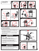
General Safety Information cont. 1 3 2 4 7 24" 8 5 6 General Installation • Installation must conform with local codes or, in the absence of local codes, with either the National Fuel Gas Code, ANSI Z223.1 (USA), CAN/CGA-B149.1, Natural Gas Installation Code or CAN/CGA-B149.2, Propane Installation Code (Canada). To check local codes, see your local L.P. gas dealer or natural gas company listed in the Yellow Pages for recommended installation procedures and regulations.
Electrical Attachments When using an electric attachment with grill, follow specification and warning statements accompanying the attachment. IMPORTANT: If using an external electrical source, the installed appliance must be electrically grounded according to local codes or, in the absence of local codes, with the National Electrical Code, ANSI/NFPA 70 or the Canadian Electrical Code CSA C22.1.
L.P. Gas Cylinder DANGER • DO NOT insert any foreign objects into the valve outlet. You may damage the valve. A damaged valve can cause a leak, which could result in explosion, fire, severe personal injury or death. WARNING • Cylinders must be stored outdoors out of the reach of children and must not be stored in a building, garage or any other enclosed area. (Fig. 11) Cylinder Specifications • Any L.P. gas supply cylinder used with this grill must be approximately 12 inches diameter and 18 inches high.
Transporting the Cylinder cont. Filling and Purging Type 1 L.P. Gas Cylinders cont. WARNING Handle a full cylinder with care. Gas is under high pressure. 13 CGA-510 POL DANGER • NEVER store a spare L.P. gas supply cylinder under the grill body or inside grill enclosure or in the vicinity of any heat producing appliance. (Fig. 12) • NEVER fill the cylinder beyond 80% full. Failure to follow this information exactly could result in an explosion and/or fire causing death or serious injury.
Assembly/Set up ■ Remove components from package.
Ö NOTE: Use a large piece of cardboard or a ground cloth to protect the painted finish on the grill. Step 1 1-A Right Panel Hardware shown actual size (TN) M6 x 15mm Screw (10) Qty. TN Base Left Panel 1-A. Arrange the two panels and the base on the ground as shown. Ö LOOSELY assemble the Right Panel and the Left Panel to the Grill Base using one screw (TN) in each top corner. 1-C 1-B TN (x2) Left Panel Flange TN (x2) TN (x2) 1-B.
Ö Step 2 Carefully turn the assembly up-side-down to perform Step 2. This will give easy access to assemble the parts in Step 2. Hardware shown actual size 2-C TN (x2) (TN) M6 x 15mm Screw (8) Qty. 2-A Base (up-side-down) 2-A. Carefully turn the grill Up-Side-Down. 2-A. Carefully turn the grill Up-Side-Down. See Detail 2-C 2-B TN (x4) 2-D Locking Casters NonLocking Casters Front TN (x4) Back 2-B. Assemble eight additional screws (TN) to fasten the Side Panels to the base Base.
Ö Step 3 NOTE: Use a ground cloth to protect the paint finish during this step. 4-A AV (x2) BW (x2) 3-A Electronic Module 4-A. Attach the Electronic Module to the Left Panel on the inside surface. Use two screws (AV) and two locking hex nuts (BW). 4-B. Assemble the Cylinder Retaining Bolt to the Cylinder Support. 4-B 2-A. Carefully turn the grill Up-Side-Down. Locking Casters 3-A. Check that all fasteners are tightened before turning the grill Right-Side-Up. Ö Carefully turn the grill Right-Side-Up.
Ö Ö Step 5 Assemble the Top Panel. Assemble the Rear Support. Ö Install Door Magnets. Step 6 Hardware shown actual size Hardware shown actual size (TN) M6 x 15mm Screw (16) Qty. (TN) M6 x 15mm Screw (4) Qty. 5-A (UO) M6 Locking Hex Nut (2) Qty. 6-A Door Magnet Top Panel TN (x2) UO (x2) TN (x8) 5-A. Assemble the Top Panel to the Left and Right Side Panels with eight Screws (TN). 5-B Rear Support 6-A.
Ö Step 7 Ö 7-B NOTE: Use a ground cloth to protect the paint finish during Step 7 and 8. Assemble Right Side Table to the Firebox. Hardware shown actual size (CX) M6 x 20mm Screw (5) Qty. CX (x2) (UO) M6 Locking Hex Nut (1) Qty. 7-C CX 7-A UO FIREBOX RIGHT SIDE TABLE 7-A. Lay the Firebox on it’s backside with lid closed . This will allow easy access to the fastener locations. Ö Assemble the Right Side Table to the Firebox with five Screws (CX) and one Locking Hex Nut (UO).
Ö 8-B Assemble Left Side Burner Assembly to the Firebox. Step 8 CX (x2) Hardware shown actual size (CX) M6 x 20mm Screw (5) Qty. (UO) M6 Locking Hex Nut (1) Qty. 8-C 8-A FIREBOX UO CX 8-D Left Side Burner Table 8-A. Assemble the Left Side Burner Table to the Firebox with five Screws (CX) and one Locking Hex Nut (UO). Place the Locking Hex Nut in the center position as shown in 8-C. Ö Tighten all fasteners.
Ö Step 9 Ö Assemble Firebox to the Grill Cart. HINT: A second person is helpful when aligning the Firebox to the Grill Cart. 9-C 9-A FIREBOX 9-C. Make sure the Firebox panel is located on the INSIDE of the Left Panel. GRILL CART 9-A. Carefully place the Firebox onto the Cart Assembly. Take care to not damage the fuel hoses. They must be routed through the large hole in the top panel. See Step 9-B. 9-D 9-B 9-D. Make sure the Firebox panel is located on the INSIDE of the Right Panel. 9-B.
Ö Fasten the Firebox to the Grill Cart. Hardware shown actual size Step 10 (TN) M6 x 15mm Screw (6) Qty. (DY) M6 Flat Washer (4) Qty. (UO) M6 Locking Hex Nut (4) Qty. 10-A TN (x3) UO (x2) DY (x2) 10-A. LOOSELY fasten the right side of the Firebox to the Grill Cart with three Screws (TN), two Flat Washers (DY) and two Locking Hex Nuts (UO). Ö NOTE: You will tighten these screws LATER (after Step 10-B), after the left side of the Firebox is attached to the Grill Cart (this helps with alignment).
Ö Fasten the Rear Trim Plate to the Grill Cart. Step 11 Hardware shown actual size (VP) Self Tapping Screw (2) Qty. 11-A FIREBOX REAR TRIM PLATE 11-B REAR TRIM PLATE VP (x2) 11-B. View showing Rear Trim Plate properly installed. 11-A. Fasten the Rear Trim Plate to the Firebox with two Screws (VP). Ö Tighten all fasteners.
Ö Step 12 Ö Fasten both Left and Right Doors to the Grill Cart. Attach the Tool Hook to the Right Door. Hardware shown actual size (XR) M5 x 15mm Flat Head Screw (8) Qty. 12-A 12-C TOOL HOOK XR (x4) LEFT DOOR RIGHT DOOR 12-C. Fasten the Right Door to the Grill Cart with four Flat Head Screws (XR). Ö Repeat Step 12-C to attach the Left Door. Ö Tighten all fasteners. 5-B TOOL HOOK 12-B. Squeeze the Tool Hook to slip into the mounting brackets.
Ö Ö Step 13 13-A Ö Install three Heat Tents™. Install three Cooking Grates. Install the Warming Rack. Warming Rack 13-B Heat Tents™ 13-B. Install three Heat Tents™ over the Burners. Ö The Heat Tents™ are located using the alignment pins. 13-C Cooking Grates Standard Grate Power Grate Standard Grate Heat Tents™ Burners 13-C. Install three Cooking Grates, flat side downward. Ö Locate the Power Grate in the center position. 13-D 18 Warming Rack 13-D.
Ö Install the Side Burner Valve. Step 14 Hardware shown actual size (WQ) M4 X 10mm Screw (2) Qty. 14-A 14-B Side Burner Valve Large Hole 14-D 14-A. Route the Side Burner Valve through the Large Hole in the Left Panel. 14-C View from Above WQ (x2) 14-E Side Burner Valve View From Back of Grill 14-C. Attach the Side Burner Valve with two Screws (WQ).
Ö Step 15 Ö Assemble the Side Burner to the Left Side Table. Assemble the Electrode to the Side Burner. 15-A Hardware shown actual size (ZT) (WQ) Hair Pin M4 X 10mm Screw (1) Qty. (1) Qty. (Attached to Burner) (YS) M4 Hex Nut (1) Qty. 15-C ZT YS WQ 15-A. Slip the Burner Tube through the Left Side Table. 15-B Burner Valve 15-B. Align Burner Tube with Burner Valve. Ö NOTE: Make sure Burner Valve is inserted into Burner Tube. 20 15-C. Lock the Side Burner in place with one hairpin (SS).
Assemble the Electrode Wires and the Battery to the Electrode Module. Note: The fuel hoses are not shown in this step, for simplicity. Ö Step 16 16-A Top Burner Wires 9-Volt Battery Electrode Module 16-A. Slip the Top Burner Wires through the large hole in the Top Panel. Ö Slip the Side Burner Wire through the large hole in the Left Panel. Ö Assemble the 9-Volt Battery to the Electrode Module. Note: The polarity is marked on the Electrode Module.
Ö Step 17 Install Side Burner Knob and Side Burner Grate onto the Left Side Burner. Assemble the Grease Cup Support to the Grease Pan. Note: The Grease Pan is shown up-side-down during this step. Ö Step 18 Hardware shown actual size (VP) Self Tapping Screw (2) Qty. 18-A 17-A Side Burner Grate Side Burner Knob VP (x2) Grease Cup Support Note: Small Surface here. Grease Pan 17-A. Place the Side Burner Knob on the valve stem. Ö Place the Side Burner Grate on the Left Side Burner.
Ö Ö Install the Grease Pan. Install the Grease Cup. Step 19 19-A Grease Pan Rear Support 19-A. Slide the Grease Pan Assembly into the back of the grill. Ö Tilt the pan slightly upward until the Grease Cup Support clears the Rear Support. 19-B Grease Cup 19-B. Place the Grease Cup into the Grease Cup Support. Note: Pull the Grease Pan outward slightly for easier access when installing/removing the Grease Cup.
NOTE: Step 20 applies to you only if your grill is set up from the factory to use LP GAS. If your grill is set up from the factory to use NATURAL GAS, skip to Step 21. Ö Attach an LP Cylinder to the Grill. 20-C Step 20 20-A LP Cylinder Type 1 Nipple Cylinder Support 20-A. Set LP Cylinder in the Cylinder Support with the outlet valve facing toward the front of the grill. Fuel Valve Outlet 20-C. Insert the TYPE 1 Nipple of the regulator into the cylinder’s Fuel Valve Outlet as shown.
NOTE: Step 21 applies to you only if your grill is set up from the factory to use NATURAL GAS. If your grill is set up from the factory to use LP GAS, skip back to Step 20. Ö Ö Attach a NATURAL GAS line to the grill. Step 21 YOUR NATURAL GAS COMPANY MUST INSTALL AND CONNECT THE GAS SUPPLY LINE TO THE GRILL. 21-A PLACE THE RUBBER PLUG ONTO THE GAS SUPPLY LINE. THEN ATTACH THE SOCKET END OF THE QUICK DISCONNECT COUPLING ONTO THE GAS SUPPLY LINE. TIGHTEN WITH A WRENCH.
Connecting Type 1 L.P. Gas Cylinders WARNING This procedure MUST be performed OUTDOORS only! Be sure L.P. cylinder valve is closed. Attach to Grill. Read and follow directions on the cylinder and fuel hose safety tags. CAUTION In the connection process, the grill side of the connection will seal on the back-check in the valve, resulting in a slight resistance. The connection requires about one-half to threequarters additional turn to complete the connection. To disconnect, turn counterclockwise.
Fixing A Fuel Leak (cont.) Lighting Instructions WARNING CAUTION Inspect the gas supply hoses before each use. If there are cuts, damage, excessive abrasion or wear, replace the hoses prior to operating the appliance. During assembly of grill and when attaching or replacing the L. P. gas cylinder, insure that all gas supply hoses are free of kinks and/or damage and are at least 3" away from hot surfaces such as the grill housing. Use only hose replacements specified in the parts list.
Lighting Main Burners Shutting Off the Grill 1. Turn on any or all burner gas control knobs to high. (Fig. 19) 2. Press the igniter switch until the flame ignites. 3. If the flame doesn’t immediately light, turn off control knob and wait five minutes for gas to clear. 4. Repeat steps 1 through 3. 5. If the burner does not light on second try, turn off knob and try match-lighting the burner. Match Lighting - Main Burners 1. Strike and place the burning match near the BURNER being operated. 2.
In Case of Grease Fire General Use and Correct Burner Flames cont. 21 Follow These Steps: Yellow Good Bad Yellow Blue Blue 1. Shut off gas at the burner valve(s) and stay away! 2. Allow the fire to burn itself out. 3. Once the fire is out and the appliance has cooled, shut off the L.P. cylinder valve. 4. Clean all parts and inspect for damage. Parts to check for damage are the L.P. cylinder, cylinder valve, regulator, gas supply hose, burner valve(s) and burner(s). 5.
Cleaning the Venturi WARNING Spider’s nests or wasp’s mud inside the venturi may cause fire at valve. If a fire occurs, immediately turn off gas supply at L.P. cylinder valve (see representative illustration in Fig. 22). If your grill is set up for use with Natural Gas, turn off gas supply at the system manual shut off valve. Note: Spiders and small insects can spin webs and build nests inside the venturi tubes. This especially occurs in late summer and fall before frost when spiders are most active.
Cleaning and Maintenance Moving and Storage cont. CAUTION A collision with the grill, as with any metal object, could cause injury. Use care when moving a portable gas grill. DANGER NEVER attempt to operate your grill without orifices in the valves. A serious and immediate fire hazard would result. Moving the grill: • • Move grill slowly. DO NOT run with or pull the grill behind you; it could hit you from behind causing injury.
Troubleshooting cont. Problem: Flame blows out on low setting or has uneven heat distribution. Possible Causes and Solutions: 1. Check for spider webs or insect nest in venturi and clean venturi. 2. Cold grill needs to be preheated for 5 minutes on high setting. 3. Venturi may be misaligned and needs to be lined up over orifices. 4. Cold and windy weather will require you to move grill away from the wind. 5. Lack of fuel. Check to see cylinder valve is open and cylinder has fuel. Problem: Grill too hot.
ATTN: DEPT 586 PRODUCT REGISTRATION DEPARTMENT PO BOX 2931 WICHITA ,KS 67201 Please Place First-Class Stamp Here Please do not send other correspondence to the address below. PLEASE FOLD AND SEAL WITH TAPE. DO NOT STAPLE.
CONGRATULATIONS ON YOUR NEW COLEMAN® GRILL PURCHASE! If you have any questions about your product, please call Coleman Customer Service at 1-800-835-3278. For easier/faster warranty registration, please go to the warranty registration section of our Coleman Web site at www.coleman.com. 1 1. Mr. 2. Mrs. 3. Ms. 4. Miss. First Name: Initial: Last Name: Address (Number and Street): Apt #: City: State: Zip: Phone #: 2 3 Date of Purchase: Month Day Year Purchase Price: $ 1.
Recipes Lemongrass beef skewers with peanut dipping sauce Lamb grilled with rosemary and Dijon Cooking time after marination: 30-40 minutes Cooking time after marination: 4-5 minutes 2 pounds boneless sirloin For the Marinade: 3 cloves garlic, minced 2 stalks lemongrass, trimmed of tough outer layer, sliced (find in Asian markets) 2 Tb sugar 1 Tb soy sauce 3 Tb thai fish sauce (find in Asian markets) 1.
Warranty Coleman Gas Barbecue Grill Limited Warranty Castings and Burners - Limited Lifetime Electronic Ignition Components - Limited Five (5) Years Cooking Surfaces and Other Parts - Limited Three (3) Years The Coleman Company, Inc. (“Coleman”) warrants that this product will be free from defects in material and workmanship.