Gas Barbecue Use, Care & Assembly Manual With Grill Lighting Instructions 5600 LP Gas Series 5610 Natural Gas Series ASSEMBLER/INSTALLER: Leave these instructions with the consumer. CONSUMER/USER: Read all instructions and keep in a safe place for future reference. For Outdoor Use Only www.coleman.com IMPORTANT Read this manual carefully before assembling, using or servicing this grill. Keep this manual for future reference.
Contents WARNING General Safety Information . . . . . . . . . . . . . . . . . . . . . . . . . . . . . . . . . . . . . . . . 2 General Installation . . . . . . . . . . . . . . . . . . . . . . . . . . . . . . . . . . . . . . . . . . . . . . 3 Electrical Attachments . . . . . . . . . . . . . . . . . . . . . . . . . . . . . . . . . . . . . . . . . . . . 4 Fuel Connections Other Than Portable L.P. Cylinders . . . . . . . . . . . . . . . . . . . 4 Portable L.P. Gas Barbecue Cylinders . . . . . . . . . . . . . .
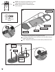
General Safety Information cont. 1 3 2 4 7 36" 8 5 6 General Installation • Installation must conform with local codes or, in the absence of local codes, with either the National Fuel Gas Code, ANSI Z223.1 (USA), CAN/CGA-B149.1, Natural Gas Installation Code or CAN/CGA-B149.2, Propane Installation Code (Canada). To check local codes, see your local L.P. gas dealer or natural gas company listed in the Yellow Pages for recommended installation procedures and regulations.
Electrical Attachments When using an electric attachment with grill, follow specification and warning statements accompanying the attachment. IMPORTANT: If using an external electrical source, the installed appliance must be electrically grounded according to local codes or, in the absence of local codes, with the National Electrical Code, ANSI/NFPA 70 or the Canadian Electrical Code CSA C22.1.
L.P. Gas Cylinder DANGER • DO NOT insert any foreign objects into the valve outlet. You may damage the valve. A damaged valve can cause a leak, which could result in explosion, fire, severe personal injury or death. WARNING • Cylinders must be stored outdoors out of the reach of children and must not be stored in a building, garage or any other enclosed area. (Fig. 11) Cylinder Specifications • Any L.P. gas supply cylinder used with this grill must be approximately 12 inches diameter and 18 inches high.
Transporting the Cylinder cont. Filling and Purging Type 1 L.P. Gas Cylinders cont. WARNING Handle a full cylinder with care. Gas is under high pressure. 13 CGA-510 POL DANGER • NEVER store a spare L.P. gas supply cylinder under the grill body or inside grill enclosure or in the vicinity of any heat producing appliance. (Fig. 12) • NEVER fill the cylinder beyond 80% full. Failure to follow this information exactly could result in an explosion and/or fire causing death or serious injury.
Assembly/Set up ■ Remove components from package.
Ö Step 1 Ö NOTE: Use a large piece of cardboard or a ground cloth to protect the painted finish on the grill. NOTE: The base pieces are assembled up-sidedown in this step. 1-A Right Base Hardware shown actual size nt Fro (TN) M6 x 15mm Screw (8) Qty. Grill Label TN Center Base TN (x8) Left Base 1-A. Arrange the three base pieces on the ground as shown. Ö Assemble the Right Base and the Left Base to the Center Base using two screws (TN) in each corner.
Ö Ö Step 2 Carefully turn the assembly Right-Side-Up. Engage the Locking Casters to prevent movement during the rest of the assembly process. 2-A. Assemble the Cylinder Retaining Bolt to the Cylinder Support. 2-A Ö Ö Step 3 Hardware shown actual size (TN) M6 x 15mm Screw (4) Qty. Hardware shown actual size (VP) Self Tapping Screw (1) Qty. 2-B 2-B. Assemble the Cylinder Support to the Base by engaging the tabs in the slots. Secure the support with one screw (VP).
Ö Assemble two Cart Spacers to the Grill Cart. Hardware shown actual size Step 4 4-A (TN) M6 x 15mm Screw (8) Qty. Cart Spacer TN (x8) 4-A. Assemble two Cart Spacers between the Left and Right Panels using eight Screws (TN). Ö NOTE: The Cart Spacers are identical. Assemble one vertically and one horizontally. Ö Tighten all fasteners. Back View of Grill from Rear Cart Spacer 4-B 4-B. View of Cart Spacers properly assembled.
Ö Step 5 Install Rear Panels. Ö Hardware shown actual size Step 6 (TN) M6 x 15mm Screw (8) Qty. 5-A Install Door Magnets. Hardware shown actual size TN (x8) (TN) M6 x 15mm Screw (4) Qty. Rear Panel (UO) M6 Locking Hex Nut (4) Qty. 6-A Door Magnet Rear Panel UO (x2) TN (x2) Fron t Fro nt 5-A. Assemble two Rear Panels to the cart assembly using eight Screws (TN). Ö NOTE: The Rear Panels are identical.
Ö Ö Step 7 Assemble Firebox to the Grill Cart. NOTE: A second person is needed when aligning the Firebox to the Grill Cart. 7-A Firebox Front Grill Cart 7-A. Carefully place the Firebox onto the Cart Assembly. Do not damage the Electrical Wires (see Fig. 7-B and 7-C). The Electrical Wires must be routed through the openings near the front and back of the Firebox.
Fasten the Firebox to the Grill Cart. NOTE: In Fig. 8-A and 8-B, the Cart Spacer is not illustrated. Ö Step 8 Hardware shown actual size (TN) M6 x 15mm Screw (4) Qty. 8-A Firebox (DY) M6 Flat Washer (4) Qty. 8-A. Lower the Firebox until it is supported by the flanges on the Right and Left Side Panels. Ö LOOSELY fasten the Firebox to the Right Side Panel with two Flat Washers (DY) and two Screws (TN) as shown in Fig. 8-A.
Ö Step 9 9-A Ö NOTE: The Grill Lids should be opened for Step 9. Assemble Right Side Table to the Grill. Firebox Hardware shown actual size (TN) M6 x 15mm Screw (4) Qty. Right Side Table 9-A. Raise the Grill Lids. Ö Place the Right Side Table against the Firebox and on top of the Right Rear Panel. Right Rear Panel 9-C Flange 9-B TN (x4) 9-B. LOOSELY install four Screws (TN) upward through the Flange of the Right Rear Panel into the Right Side Table.
Ö Assemble Right Side Table to the Grill (continued). Hardware shown actual size Step 10 (TN) M6 x 15mm Screw (4) Qty. (DY) M6 Flat Washer (2) Qty. 10-A. LOOSELY assemble two additional Screws (TN) and two Flat Washers (DY) through the Firebox into the Right Side Table at the rear of the grill. 10-A 10-B TN (x2) DY (x2) View of Grill from Rear 10-C 10-C. Assemble two additional Screws (TN) through the Right Side Table into the Firebox at the front of the grill. Ö Tighten all fasteners.
Ö Step 11 11-A Left Fryer Assembly Ö NOTE: The Grill Lids must be opened for Step 11. Assemble Left Fryer Assembly to the Grill. Hardware shown actual size (TN) M6 x 15mm Screw (1) Qty. 11-A. Raise the Grill Lids. Ö Place the Left Fryer Assembly against the Firebox and on top of the Left Rear Panel. 11-C Left Rear Panel 11-B Flange TN 11-B. Align three studs from Left Fryer Assembly with slots in flange of the Left Rear Panel.
Ö Step 12 Assemble Left Fryer Assembly to the Grill (continued). Hardware shown actual size (TN) M6 x 15mm Screw (4) Qty. (DY) M6 Flat Washer (2) Qty. 12-A. LOOSELY assemble two additional Screws (TN) and two Flatwashers (DY) through the Firebox into the Left Fryer Assembly at the rear of the grill. 12-A 12-B TN (x2) DY (x2) View of Grill from Rear 12-C 12-C. Assemble two additional Screws (TN) through the Left Fryer Assembly into the Firebox at the front of the grill. Ö Tighten all fasteners.
Ö Step 13 Assemble the Fuel Hose Fitting from the Grill to the Fryer Assembly. 13-B Collar on the Quick Coupler 13-A Male Hose Fitting 13-B. Retract the Collar on the Quick Coupler before inserting the Male Hose Fitting. Fully insert the Male Hose Ö Fitting into the Quick Coupler. Release the Collar to lock Ö the connection. Fuel Hose from Fryer Assembly 13-A. Assemble the Fuel Hose Fitting from the Grill to the Fryer Assembly.
Ö Step 14 Ö 14-A Assemble the Electrode Wire to the Electrode Tip on the Side Fryer. Assemble the Grease Pan below the Fryer Burner. Route the Electrode Wire through the slot in the Fryer Panel. Electrode Wire Electrode Tip Fryer Panel Left Side Panel 14-A. Attach the Electrode Wire to the Electrode Tip on the Side Fryer. 14-B Hooks Fryer Grease Pan 14-B. Attach Fryer Grease Pan using four hooks located below the Fryer Burner.
Ö Assemble Front Fryer Heat Shield. Step 15 15-A Electrode Wire Engage Tabs into Rectangle Holes Fryer Heat Shield 15-A. Assemble Fryer Heat Shield. NOTE: Place the Fryer Heat Shield between the Fryer Panel and the Flexible Fuel Ö Hose. Do not pinch Electrode Wire. Engage the two tabs on the Heat Shield downward into the rectangle holes. Ö 15-B Fryer Heat Shield 15-B. View showing the Fryer Heat Shield properly installed.
Ö Step 16 Ö Route the Electrical Wires under the Right Side Table. Note the location of the Electrode Module. 16-B Electrical Wire Wire Support 16-A Electrode Module Back Burner Electrical Wire 16-A. Route the Back Burner Electrical Wire through the Wire Support. 16-C 16-D Wire Tie Electrical Wire 16-C. Route the Main Burner Electrical Wires through the Wire Tie. Wrap the Wire Tie around the wire and secure in place.
Ö Step 17 Assemble the electrode Wires and the Battery to the Electrode Module. 17-A Electrode Module 9-Volt Battery Igniter Button Wires (Note: Large Tabs) Back Burner Electrode Wire 17-A. Firmly push the Electrode Wires into the Electrode Module. Assemble the 9-Volt Battery to the Electrode Module. Ö NOTE: The polarity is marked on the Electrode Module. Ö TEST THE IGNITER: A SPARK SHOULD APPEAR AT ELECTRODE TIP. IF THE SPARK DOES NOT APPEAR: -CHECK THE WIRE CONNECTIONS TO THE MODULE.
Ö Fasten the Rear Trim Plate to the Grill Cart. Step 18 Hardware shown actual size (VP) Self Tapping Screw (2) Qty. 18-A FIREBOX REAR TRIM PLATE VP (x2) 18-B VP 18-A. Fasten the Rear Trim Plate to the Firebox with two Screws (VP). Ö NOTE: Route Electrical Wire through notch. Do not pinch wire. Ö Tighten all fasteners. 18-C ROUTE ELECTRICAL WIRE THROUGH NOTCH -DO NOT PINCH- REAR TRIM PLATE 18-C. View showing Rear Trim Plate properly installed.
Ö Step 19 Ö Fasten both Left and Right Doors to the Grill Cart. Attach the Tool Hook to the Right Door. Hardware shown actual size (XR) M5 x 15mm Flat Head Screw (8) Qty. 19-A TOOL HOOK 19-C TOOL HOOK Brackets LEFT DOOR (without Tool Hook Brackets) RIGHT DOOR (with Tool Hook Brackets) 19-B 19-C. Squeeze the Tool Hook to slip into the mounting brackets. XR (x4) 19-B. Fasten the Right Door to the Grill Cart with four Flat Head Screws (XR). Ö NOTE: Right Door has Tool Hook Brackets.
Ö Ö Step 20 Ö Fasten the Door Handles to the Doors. Attach the Tool Hook to the Right Door. NOTE: M4 x 5mm Screws are factory installed into the Handles. Step 21 21-A Hardware shown actual size Ö Ö Ö Install four Heat Tents™. Install four Cooking Grates. Install two Warming Racks. Warming Racks Cooking Grates (EZ) M4 X 5mm Screw (4) Qty. Heat Tents™ 20-A EZ (x2) Burners RIGHT DOOR DOOR HANDLE 20-A. Fasten one Door Handle to the Right Door with two Screws (EZ).
21-B Ö Heat Tents™ Step 22 22-A Place Basket and Thermometer in the Fryer Assembly. Fryer Basket 21-B. Install four Heat Tents™ over the Burners. Ö The Heat Tents™ are located using the alignment pins. 21-C Standard Grate Power Grates Standard Grate Thermometer 21-C. Install four Cooking Grates with smooth surface down. Ö Locate the Power Grates in the center positions. 21-D 22-A. Place the Basket and Thermometer in the Fryer Assembly.
Assemble two Grease Cup Supports to the Grease Pan. Note: The Grease Pan is shown up-side-down during this step. Ö Step 23 Hardware shown actual size Ö Ö Install the Grease Pan. Install two Grease Cups. Step 24 24-A Grease Pan (VP) Self Tapping Screw (4) Qty. 23-A Grease Cup Support VP (x4) Grease Pan 24-A. Slide the Grease Pan Assembly into the back of the grill. Note: Flange is down. 24-B Note: Lip is up. Grease Cup 23-A.
Ö Step 25 Ö Assemble the Motor Mount Bracket to the right outside of the Firebox. Assemble the Rotisserie to the Firebox. 25-C NOTE: Machined Groove Toward Handle Slip Collar Fork Spit Rod Hardware shown actual size Handle Set Collar (UO) M6 Locking Hex Nut (2) Qty. (TN) M6 x 15mm Screw (2) Qty. 25-A Fork Pointed Tip 25-C. Loosely assemble the Rotisserie parts as shown in Figure 25-C. Do not tighten the thumbscrews until properly positioned in step 25-D.
25-E Push Button to Remove Rotisserie Handle 25-E. Remove Handle immediately after placing Rotisserie into the Firebox. Damage will occur if the Handle is not removed prior to cooking. CAUTION • DO NOT OPERATE THE GRILL WITH THE ROTISSERIE HANDLE ON THE SPIT ROD.
NOTE: Step 26 applies to you only if your grill is set up from the factory to use LP GAS. If your grill is set up from the factory to use NATURAL GAS, skip to Step 27. Ö Attach an LP Cylinder to the Grill. 26-C Step 26 26-A LP Cylinder Type 1 Nipple Fuel Valve Outlet Cylinder Support 26-A. Set LP Cylinder in the Cylinder Support with the outlet valve facing toward the front of the grill. 26-C. Insert the TYPE 1 Nipple of the regulator into the cylinder’s Fuel Valve Outlet as shown.
NOTE: Step 27 applies to you only if your grill is set up from the factory to use NATURAL GAS. If your grill is set up from the factory to use LP GAS, skip back to Step 26. Ö Ö Attach a NATURAL GAS line to the grill. Step 27 YOUR NATURAL GAS COMPANY MUST INSTALL AND CONNECT THE GAS SUPPLY LINE TO THE GRILL. 27-A PLACE THE RUBBER PLUG ONTO THE GAS SUPPLY LINE. THEN ATTACH THE SOCKET END OF THE QUICK DISCONNECT COUPLING ONTO THE GAS SUPPLY LINE. TIGHTEN WITH A WRENCH.
Connecting Type 1 L.P. Gas Cylinders WARNING This procedure MUST be performed OUTDOORS only! Be sure L.P. cylinder valve is closed. Attach to Grill. Read and follow directions on the cylinder and fuel hose safety tags. CAUTION In the connection process, the grill side of the connection will seal on the back-check in the valve, resulting in a slight resistance. The connection requires about one-half to three-quarters additional turn to complete the connection. To disconnect, turn counterclockwise.
Fixing A Fuel Leak (cont.) Lighting Instructions WARNING CAUTION Inspect the gas supply hoses before each use. If there are cuts, damage, excessive abrasion or wear, replace the hoses prior to operating the appliance. During assembly of grill and when attaching or replacing the L. P. gas cylinder, insure that all gas supply hoses are free of kinks and/or damage and are at least 3" away from hot surfaces such as the grill housing. Use only hose replacements specified in the parts list.
Lighting Main Burners Igniter Lighting Fryer Burner Lighting Igniter Lighting: 1. Turn on any or all main burner gas control knobs to high. (Fig. 19) 2. Press the igniter switch until the flame ignites. 3. If the flame does not immediately light, turn off control knobs and wait five minutes for gas to clear. 4. Repeat steps 1 through 3. 5. If the burner does not light on second try, turn off knobs and try match-lighting the burner. Match Lighting CAUTION Use a LONG wooden match.
General Use and Correct Burner Flames Grilling Tips and Hints Burner Control Setting Tips WARNING • Keep grill area clean and free from combustible materials, gasoline and other flammable vapors, liquids, and spare L.P. cylinders. • DO NOT obstruct the flow of combustion and ventilation air. • Keep the ventilation opening(s) of the L.P. cylinder enclosure free and clear of debris. • A barbecue grill becomes hot during use. DO NOT touch grates, or cooking surfaces.
Cooking Methods Direct Method: • The heat source is directly below the food. • Use for browning meat or cooking hot dogs and hamburgers, but check food frequently. • Use for skillet and stir-fry cooking, but limit the amount of oil and heat to be used. • Cook roasts, turkey or duck on low heat. Place meat with water in foil pan with corrugated bottom. Replenish water as needed. Indirect Method: • Light only one side of the burner and place food on opposite side for cooking.
Cleaning and Maintenance Moving and Storage CAUTION CAUTION All cleaning and maintenance should be done only when grill is cool & with the fuel supply turned off at the cylinder. If your grill is set up for use with Natural Gas, turn off gas supply at the system manual shut off valve. A collision with the grill, as with any metal object, could cause injury. Use care when moving a portable gas grill.
Troubleshooting cont. Problem: Flame blows out on low setting or has uneven heat distribution. Possible Causes and Solutions: 1. Check for spider webs or insect nest in venturi and clean venturi. 2. Cold grill needs to be preheated for 5 minutes on high setting. 3. Venturi may be misaligned and needs to be lined up over orifices. 4. Cold and windy weather will require you to move grill away from the wind. 5. Lack of fuel. Check to see cylinder valve is open and cylinder has fuel. Problem: Grill too hot.
ATTN: DEPT 586 PRODUCT REGISTRATION DEPARTMENT PO BOX 2931 WICHITA ,KS 67201 Please Place First-Class Stamp Here Please do not send other correspondence to the address below. PLEASE FOLD AND SEAL WITH TAPE. DO NOT STAPLE.
CONGRATULATIONS ON YOUR NEW COLEMAN® GRILL PURCHASE! If you have any questions about your product, please call Coleman Customer Service at 1-800-835-3278. For easier/faster warranty registration, please go to the warranty registration section of our Coleman Web site at www.coleman.com. 1 1. Mr. 2. Mrs. 3. Ms. 4. Miss. First Name: Initial: Last Name: Address (Number and Street): Apt #: City: State: Zip: Phone #: 2 3 Date of Purchase: Month Day Year Purchase Price: $ 1.
Recipes Spice-rubbed spareribs Grilled tuna steaks with olive vinaigrette Cooking time: 45 minutes to partial boil; 16-20 minutes to grill Cooking time after marination: 10 minutes 4 6-8 oz. Tuna steaks 6 pounds baby back pork spareribs water to cover For the spice mixture: 2 Tb brown sugar 3 Tb paprika 1 Tb chili powder 1 tsp garlic powder 2 tsp black pepper 1 Tb Dijon mustard 1 Tb salt 1 cup bottled barbeque sauce, to brush over ribs Put the ribs in a very large stockpot on the burner.
Recipes Asian-flavored eggplant Chili-orange pork loin Cooking time: 8-10 minutes Cooking time after marination: 6-7 minutes 2 large eggplant, peeled and sliced into 1/2 inch rounds 2 Tb olive oil 2 pounds boneless pork loin, cut into 16 thin slices 1/2 cup orange juice juice of one lime 4 cloves garlic, minced 1 serrano chili, minced 2 Tb chili powder 1 Tb sugar 1 tsp salt 1 tsp dried oregano 1 Tb olive oil For the sauce: 1 tsp grated ginger 3 cloves minced garlic 4 green onions, sliced thin 2 Tb so
Recipes Lemongrass beef skewers with peanut dipping sauce Lamb grilled with rosemary and Dijon Cooking time after marination: 30-40 minutes Cooking time after marination: 4-5 minutes 2 pounds boneless sirloin For the Marinade: 3 cloves garlic, minced 2 stalks lemongrass, trimmed of tough outer layer, sliced (find in Asian markets) 2 Tb sugar 1 Tb soy sauce 3 Tb thai fish sauce (find in Asian markets) 1.
Warranty Coleman Gas Barbecue Grill Limited Warranty Castings and Burners - Limited Lifetime Electronic Ignition Components - Limited Ten (10) Years Cooking Surfaces and Other Parts - Limited Five (5) Years The Coleman Company, Inc. (“Coleman”) warrants that this product will be free from defects in material and workmanship.