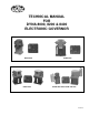
TECHNICAL MANUAL FOR DYNA 8000, 8200 & 8400 ELECTRONIC GOVERNOR DYNA 8000 DYNA 8400 DYNA 8200 DYNA 8000-400 & DYNA 8400-400 F-23721-5
CONTENTS SECTION DESCRIPTION PAGE 1 GENERAL INFORMATION ........................... 3 2 SPECIFICATIONS......................................... 3 3 FUNCTIONAL DESCRIPTION ..................... 5 4 INSTALLATION ............................................. 6 5 CALIBRATION OF DYN1-1065X .................. 9 6 CALIBRATION OF DYN1-1068X ................ 11 7 TROUBLESHOOTING ................................ 13 8 INSTALLATION DIMENSIONS ...................
1. GENERAL INFORMATION 2.1.10 DYNA 8000 CONTROLLER 1.1 INTRODUCTION Output Current @ 12 VDC The DYNA 8000, DYNA 8200 and DYNA 8400 governor system provides an engine governor for speed and power control of piston and gas turbine engines or steam and water turbines. Output Current @ 24 VDC Weight The actuator is a simple, proportional, electric solenoid having a sliding armature whose magnetic force is proportional to input coil current.
2.2.7 AVAILABLE DYNA 8000 ACTUATOR MODELS WITH CLOCKWISE OUTPUT SHAFT ROTATION (Standard Mounted Units) • DYNC-11020-000-0-12 Standard Clockwise DYNC-11020-000-0-24 Output Shaft Rotation 2.2.
Work Torque Output Weight Current@ 12 VDC Current @ 24 VDC Joules Foot-Pounds Newton-Meters Pound-Foot Rotary Kilograms Pounds Maximum Amperes @ Stall Nominal Steady State Amperes Maximum Amperes @ Stall Nominal Steady State Amperes 2.4.7 AVAILABLE DYNA 8400 ACTUATOR MODELS WITH TERMINAL STRIP CONNECTION 2.85 2.10 4.07 3.00 45° 8.4 18.5 14.75 4.5 14.0 3.5 Nominal Response Time for 63% of Stroke (Seconds) • 2.4.8 AVAILABLE DYNA 8400 ACTUATOR MODELS WITH 2-PIN MS SCREW ON CONNECTOR • 2.3.
3.5 ISOCHRONOUS OPERATION 3.7 REMOTE SPEED ADJUSTMENT Isochronous operation is obtained by setting droop potentiometer fully counterclockwise. The DYNA governor is all electric, and it is normally operated in the isochronous mode; i.e., engine RPM is constant (±0.25%) under steady state load conditions, up to the engine's maximum capability, regardless of load on the engine. An optional remote speed selector (DYNS-10000) is available for adjusting engine RPM from up to 90 meters (300 ft.
2 Pin Connector No.MS3106A 10-SL-4S Magnetic Pickup has 5/8-18 Threads Jam Nut Speed Sensor Engine Housing Gap Ring Gear .37 ± .127 mm [.015 ± .005] INSTALLATION OF MAGNETIC PICKUP 4.1.4 Mount the controller in the control panel. 4.1.5 Connect the wiring as shown in section 4.3 or according to your particular wiring diagram. 4.2 TYPICAL LINKAGE ARRANGEMENTS FOR THE ACTUATOR AND FUEL SYSTEM 4.2.
4.3 TYPICAL WIRING DIAGRAM & CONTROLLER INSTALLATION DIMENSIONS DIMENSIONS -- DYNA 8000 CONTROLLER -- DYN1 1065X and DYN1 1068X Dimensions are in mm except as otherwise noted. Dimensions in [ ] are in inches.
5. CALIBRATION OF DYNA 8000 SERIES CONTROLLER — DYN1-1065X Input Signal Frequency Maximum Part Number Input Signal Frequency Maximum Part Number DYN1-10652-000-0-12/24 DYN1-10652-001-0-12/24* ] 250 to 1200 Hz DYN1-10654-000-0-12/24 DYN1-10654-001-0-12/24* ] 2500 to 5000 Hz DYN1-10653-000-0-12/24 DYN1-10653-001-0-12/24* ] 1200 to 2500 Hz DYN1-10656-000-0-12/24 DYN1-10656-001-0-12/24* ] 5000 to 9000 Hz NOTE * See Step 5.
5.3 ALL CONTROLLERS WITH REVISION J AND ABOVE HAVE SWITCHES S1 AND S2 5.5 PROPER PROCEDURES FOR SETTING SWITCHES S1 AND S2 These units have two new features now added to the DYN1 1065X series controllers. They are: Question: How do I know if the switches in the dual-in-line packages are correctly set as far as being in the OFF position or the ON position? 5.3.1 Two response ranges, for matching either the diesel or gas engine dynamics.
6. CALIBRATION PROCEDURE FOR 8000 GOVERNOR CONTROLLER — DYN1-10682, 10683, 10684, 10686 Input Signal Frequency Maximum Part Number Input Signal Frequency Maximum Part Number DYN1-10682-000-0-12/24 DYN1-10682-001-0-12/24* ] 250 to 1200 Hz DYN1-10684-000-0-12/24 DYN1-10684-001-0-12/24* ] 2500 to 5000 Hz DYN1-10683-000-0-12/24 DYN1-10683-001-0-12/24* ] 1200 to 2500 Hz DYN1-10686-000-0-12/24 DYN1-10686-001-0-12/24* ] 5000 to 9000 Hz NOTE * See Step 6.
6.5 GENERAL INFORMATION ON S1 AND S2 • Switch S1 selects one of two integrating rate ranges. The diesel version integrates at twice the rate of the gas version. • Switch S2 selects the point at which actuator coil current level causes the integrator limit to be actuated. This level is nominally 6.3 amperes for the DYNA 8000 and 7.3 amperes for the DYNA 8200 and 8400 actuator. 6.
7. DYNA 8000 SERIES TROUBLESHOOTING CHART 7.1 PROBLEM: GOVERNOR IS COMPLETELY DEAD AND ACTUATOR LEVER STAYS AT MINIMUM POSITION WHEN POWER IS APPLIED TO GOVERNOR. Means of Detection Corrective Action 7.1.1 Check battery voltage at terminals 1 and 2 on controller. Terminal 1 is positive. Check battery connections and contacts for turning power ON to the controller. 7.1.2 Check for proper linkage setup. Correct and free linkage. 7.1.3 Magnetic pickup signal absent or too low.
7.2 PROBLEM: ACTUATOR GOES TO FULL STROKE WHEN DC POWER IS TURNED ON (ENGINE IS NOT OPERATING). Means of Detection Corrective Action 7.2.1 Check magnetic pickup leads for proper shielded wire or open shield. Verify and correct wiring as necessary. 7.2.2 Be sure there is no jumper between terminals 2 and 3. Verify and correct wiring as necessary. 7.2.3 Failsafe circuit in the controller may be damaged or defective. Replace controller. 7.2.4 With DC power OFF remove leads at actuator.
7.5 PROBLEM: SLOW, SMALL AMPLITUDE HUNTING OF SPEED OR FREQUENCY Corrective Action Means of Detection 7.5.1 Correct Linkage. Sticking or very loose linkage. 7.6 PROBLEM: FAST OSCILLATION OF GOVERNOR LINKAGE Means of Detection 7.6.1 Corrective Action Verify calibration settings of the controller. Readjust settings as necessary. 7.7 PROBLEM: ENGINE WILL NOT START -- ACTUATOR GOES TO FULL FUEL DURING CRANKING Means of Detection Corrective Action 7.7.1 Make sure fuel is available.
DYNC-11024-000 ACTUATOR — COUNTERCLOCKWISE ROTATION DYNC-11024-300 SIDE MOUNTED ACTUATOR — COUNTERCLOCKWISE ROTATION DYNC-12000-000 16
DYNC-14800-000 TERMINAL STRIP CONNECTION DYNC-14801-000 2-PIN MS CONNECTOR CONNECTION DYNC-11020-401 UL APPROVAL, HAZARDOUS DUTY, CLASS 1, DIVISION 2, GROUP D CLOCKWISE UNIT 17
DYNC-11024-400 UL APPROVAL, HAZARDOUS DUTY, CLASS 1, DIVISION 2, GROUP D COUNTERCLOCKWISE UNIT DYNC-14800-400 UL APPROVAL, HAZARDOUS DUTY, CLASS 1, DIVISION 2, GROUP D Barber-Colman DYNA Products 1354 Clifford Avenue (Zip 61111) Telephone (815) 637-3000 P.O. Box 2940 Facsimile (815) 877-0150 Loves Park, IL 61132-2940 www.dynaproducts.