
Service manual

129099-UUM-F-0507
6 Unitary Products Group
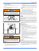
Motor Lubrication
The motors in these furnaces are permanently lubricated, and do not
require periodic oiling.
SECTION II: SERVICE AND MAINTENANCE
MANUAL
SAFETY SECTION
This section has been designed to assist a qualified service agency in
performing service and maintenance on this appliance. The homeown-
ers and/or end user must never attempt to perform any service or main-
tenance on the appliance especially when it involves the removal or
adjustment of any parts and/or components.
The following safety rules must be followed when servicing the
furnace.
FURNACE MAINTENANCE SECTION
The furnace should be cleaned and adjusted by a certified dealer or
qualified service contractor once a year or before the start of every
heating season. The following items must be cleaned and serviced or
replaced if there are signs of deterioration.
1. The roof cap (if applicable).
2. The furnace vent pipe. Should it be necessary to service the vent/
air intake system, the manufacturer recommends this service be
conducted by a qualified service agency. The operation of this
appliance requires the reassembly and resealing of the vent/air
intake system.
3. The furnace burner, ignitor and flame sensor.
FURNACE CLEANING SECTION
NOTE: The cleaning operations listed below must be performed only by
a qualified service agency.
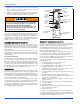
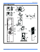
Burner Removal/Cleaning
The main burner should be checked periodically for dirt accumulation. If
cleaning is required, follow this procedure:
1. Turn off the electrical power to the unit.
2. Turn off the gas supply at the external manual shut-off valve and
loosen the ground union joint.
3. Remove the upper access panel.
4. Disconnect wires from flame sensor, rollout switch and HSI igniter.
Remove igniter carefully, as it is easily broken.
5. Remove the screws that hold the burner assembly to the combus-
tion air box and remove the assembly.
6. Remove burner from the burner assembly.
7. Rinsing in hot water may clean burners.
8. Reassemble in the reverse order.
Cleaning the Heat Exchanger
NOTE: It is recommended that replacement gaskets be available
before removing burner assembly and combustion air box.
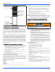
Lower Heat Exchanger Access
1. Turn off the electrical power to the unit and turn off gas supply at
the shutoff valve.
2. Remove the blower and burner compartment access doors. Dis-
connect the gas supply piping at the union to permit removal of the
entire burner and gas control assembly from the vestibule panel.
Use the wrench boss on the gas valve when removing or installing
this piping.
3. Unplug the igniter from the wire harness. Disconnect sensor wires.
Identify and note the location of all leads for ease of reinstallation.
4. Remove the screws holding the burner assembly to the vestibule
panel and remove this assembly. Handle the assembly carefully
since it contains the igniter, which is fragile and easily broken. The
lower portion of the heat exchanger will now be exposed. Remove
any soot and scale. Vacuum loose soot, scale and dirt from the
heat exchanger.
5. After cleaning is complete, replace all components in reverse
order. Re-gasket all surfaces which required a gasket. Reconnect
all wiring. Reattach vent pipe and gas supply lines before restoring
service to furnace. Restore electrical power, check gas supply pip-
ing for leaks, and then verify furnace operation.
U
THE FURNACE CONTROLS AND THEIR FUNCTION
1. Limit Control - This furnace is protected by two (2) high tempera-
ture limit switches. The lower limit switch is an automatic reset
type.
2. Upper Limit Control - The upper limit switch near left side of
blower is a manual reset type limit switch. If burner does not func-
tion, turn system switch to “OFF” and push reset button in center
of limit switch.
3. Gas Valve - The gas valve is 100% shut-off type and will fail safe if
for some reason the gas is turned off. It is also of the snap opening
type which opens to fire position.
SEQUENCE OF OPERATION
Continuous Blower
On cooling/heating thermostats with fan switch, when the fan switch is
set in the ON position, a circuit is completed between terminals R and G
of the thermostat. The blower motor is energized through the cool fan
terminal on the ignition control module.
Intermittent Blower - Cooling
On cooling/heating thermostats with fan switch, when the fan switch is
set in the auto position and the thermostat calls for cooling, a circuit is
completed between the R, Y and G terminals. The motor is energized
through the cool fan terminal and runs on the selected speed. The fan
off setting is fixed at 60 seconds for SEER enhancement.
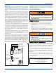
Make sure you DO NOT move the clip on weight on the
indoor fan wheel when cleaning the wheel. This weight is
used to balance the wheel. Moving the weight will cause
the fan wheel to vibrate.
ELECTRIC SHOCK, FIRE OR EXPLOSION HAZARD
Failure to follow safety warnings exactly could result in
dangerous operation, serious injury, death or property
damage.
Improper servicing could result in dangerous operation,
serious injury, and death or property damage.
• Before servicing, disconnect all electrical power to the fur-
nace.
• When servicing controls, label all wires prior to discon-
necting. Reconnect wires correctly.
• Verify proper operation after servicing.
Label all wires prior to disconnection when servicing con-
trols. Wiring errors can cause improper and dangerous
operation. Verify proper operation after servicing.