
Service manual

129099-UUM-F-0507
Unitary Products Group 7
Heating Cycle
When the system switch is set on HEAT and the fan is set on AUTO,
and the room thermostat calls for heat, a circuit is completed between
terminals R and W of the thermostat. When the proper amount of com-
bustion air is being provided, a pressure switch activates the ignition
control.
The ignition control provides a 30-second warm-up period. The gas
valve then opens for 10 seconds. If the flame is not detected within 2
seconds of the gas valve opening, the gas valve is shut off and a retry
operation begins. If the flame is lost for 2 seconds during the 10 second
stabilization period, the gas valve is shut off and a retry operation
begins. During a retry operation the ventor starts a 15 second inter-
purge and the ignitor warm-up time is extended to 27 seconds. If the
flame is established for more than 10 seconds after ignition, during a
retry, the control will clear the ignition attempt (retry) counter. If three
retries occur during a call for heat, the furnace will shut down for one
hour. If at the end of the one hour shut down there is a call for heat, the
furnace will initiate a normal start cycle. If the problem has not been cor-
rected the furnace will again lockout after three retries.
A momentary loss of gas supply, flame blowout, or a faulty flame probe
circuit will result in a disruption in the flame and be sensed within 0.8
seconds. The gas valve will de-energize and the control will begin a
recycle operation. A normal ignition sequence will begin after a 15 sec-
ond inter-purge. If during the three recycles the gas supply does not
return, or the fault condition is not corrected the ignition control will lock-
out for 60 minutes.
During burner operation, a momentary loss of power for 50 milliseconds
or longer will de-energize the gas valve. When the power is restored,
the gas valve will remain de-energized and the ignition sequence will
immediately restart.
As the gas starts to flow and ignition occurs, the flame sensor begins its
sensing function. If a flame is detected during the 10 second flame sta-
bilization period the circulating blower will energize 30 seconds after the
gas valve opens (20 seconds after the flame stabilization period ends).
Normal furnace operation will continue until the thermostat circuit
between R and W is opened. When the thermostat circuit opens, the
ignition control is de-energized. When the ignition control is de-ener-
gized, the gas flow stops, and the burner flames are extinguished. The
ventor continues to operate for 15 seconds after the gas flow stops.
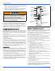
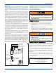
The blower motor continues to operate for the amount of time set by the
fan-off delay "Jumper" located on the ignition control board. Refer to
Figure 6. The heating cycle is complete, and the furnace is ready for the
start of the next heating cycle.
Hot Surface Ignition System
TROUBLESHOOTING
The following visual checks should be made before troubleshooting:
1. Check to see that the power to the furnace and the ignition control
module is ON.
2. The manual shut-off valves in the gas line to the furnace must be
open.
3. Make sure all wiring connections are secure.
4. Review the sequence of operation. Start the system by setting the
thermostat above the room temperature. Observe the system’s
response. Then use the troubleshooting section in this manual to
check the system’s operation.
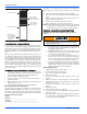
FURNACE CONTROL DIAGNOSTICS
The furnace has built-in, self diagnostic capability. If a system problem
occurs, a fault code is shown by a blinking green LED. It is located
behind a clear view port in the blower compartment door. DO NOT turn
off furnace power as this action will clear the control's memory of the
fault.
The control continuously monitors its own operation and the operation
of the system. If a failure occurs, the LED will indicate the failure code. If
the failure is internal to the control, the light will stay on continuously. In
this case, the entire control should be replaced as the control is not field
repairable.
Flash sequence codes 1 through 6 are as follows: LED will turn “on” for
one second and “off” for one second. This pattern will be repeated the
number of times equal to the code. For example, six “on” flashes equals
a number 6 fault code.
All flash code sequences are broken by a 2 second “off” period.
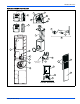
FIGURE 6: Furnace Control Board
FAN ON
ADJUSTMENT
JUMPER
HEAT
XFMR
L1
COOL
TRANSFORMER
LINE VOLTAGE
BLACK - HIGH SPEED
RED -LOW SPEED
FAN OFF
JUMPER
NEUTRALS
FUSE 3A
HOT SURFACE IGNITION SYSTEM
Do not attempt to light this furnace by hand (with a match
or any other means). There may be a potential shock haz-
ard from the components of the hot surface ignition sys-
tem. The furnace can only be lit automatically by its hot
surface ignition system.
Never bypass pressure switch to allow furnace operation.
To do so will allow furnace to operate under potentially
hazardous conditions.
Do not try to repair controls. Replace defective controls
with UPG Source 1 Parts.
Never adjust pressure switch to allow furnace operation.
IGNITION CONTROL
Normal flame sense current is approximately
3.7 microamps DC (υa)
Low flame signal control lockout point is
0.9 microamps DC (υa)