INSTALLATION INSTRUCTIONS ELDV Direct-Vent Gas Fireplaces MODELS P/N 850036M Rev. I 09/2012 This manual is one of a set of two supporting this product. Refer to P/N 875030M for Care and Operation Instructions. Ce manuel est disponible en francais, simplement en faire la demande. Numéro de la pièce 850036CF. MILLIVOLT: ELDV-35NM ELDV-40NM ELDV-45NM ELDV-35PM ELDV-40PM ELDV-45PM ™ ELECTRONIC: ELDV-35NE ELDV-40NE ELDV-45NE Portland INSTALLER: Leave this manual with the appliance.
TABLE OF CONTENTS Packaging..........................................Page Introduction.......................................Page General Information...........................Page Requirements for the Commonwealth of Massachusetts..Page New York City Approval......................Page Cold Climate Insulation......................Page Manufactured Home Requirements...Page Location.............................................Page Vent Termination Clearances .............Page Appliance and Vent Clearances....
WARNING Improper installation, adjustment, alteration, service or maintenance can cause injury or property damage. Refer to this manual. For assistance or additional information consult a qualified installer, service agency or the gas supplier. WARNING Failure to comply with these installation instructions will result in an improperly installed and operating appliance, voiding its warranty. Any change to this appliance and/or its operating controls is dangerous.
28,000 high 21,000 low *Electronic valves may be converted to propane. Table 2 These appliances must not be connected to a chimney or flue serving a separate solid fuel burning appliance. Orifice Sizes - Sea Level to High Altitude (All Models) Inlet Gas Supply Pressure (all models) For elevations above 4500 feet, contact your gas supplier or qualified service technician . Natural Gas 4.5" WC (1.12 kPa) 10.5" WC (2.61 kPa) Propane 11.0" WC (2.74 kPa) 13.0" WC (3.
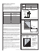
Note: When the unit is installed with one side flush with a wall, the wall on the other side of the unit must not extend beyond the front edge of the unit. TOP VENT APPLICATION APPLICATION TOP VENT TOP VENT APPLICATION TOP VENT APPLICATION AP TOP PL V IC EN AT T IO N • A hard wired carbon monoxide detector with an alarm and battery back-up must be installed on the floor level where the gas fireplace is installed.
Be aware that this is a heat producing appliance. Objects placed above the unit are exposed to elevated temperatures. Do not insulate the space between the appliance and the area above it (see Figure 8 ). Vertical Vent Termination Clearances TERMINATION HEIGHTS FOR VENTS ABOVE FLAT OR SLOPED ROOFS Horizontal Overhang 2 FT MIN. 2 FT MIN. The minimum height from the base of the appliance to the underside of combustible materials used to construct a utility shelf in this fashion is shown in Figure 8.
EXTERIOR HORIZONTAL VENT TERMINATION CLEARANCE REQUIREMENTS NOTE: Local Codes Or Regulations May Require Different Clearances. * See Item D in the Text Below. P N NOTE: Location Of The Vent Termination Must Not Interfere With Access To The Electrical Service. Inside Corner Detail Exterior Wall O *18” Horizontal Termination G V 6” N Q V V Ventilated Soffit A Inside Corner in U.S. A == 9” 12” in Canada Detail D H 3 ft.
MINIMUM CLEARANCES TO COMBUSTIBLES Appliance And Vent Clearances The appliance is approved with zero clearance to combustible materials on all sides (as detailed in Table 6 ), with the following exception: When the unit is installed with one side flush with a wall, the wall on the other side of the unit must not extend beyond the front edge of the unit. In addition, when the unit is recessed, the side walls surrounding the unit must not extend beyond the front edge of the unit (see Figure 3).
WARNING Failure to position the parts in accordance with these diagrams or failure to use only parts specifically approved with this appliance may result in property damage or personal injury. AVERTISSEMENT Risque de dommages ou de blessures si les pièces ne sont pas installées conformément à ces schémas et ou si des pièces autres que celles spécifiquement approuvées avec cet appareil sont utilisées.
FIREPLACE AND FRAMING SPECIFICATIONS Framing Vent Framing - Top Vent With One 90° Elbow Framing Dimensions Model No. ELDV35 ELDV40 ELDV45 A B C D 56-1/2 in. 35-9/16 40-5/16 21-7/16 mm 903 1024 545 1435 in. 40-9/16 40-5/16 21-7/16 56-1/2 mm 1030 1024 545 1435 in.
FIREPLACE FRAMING SPECIFICATIONS Model No. ELDV35 ELDV40 ELDV45 A B C D b E in. 35 3/16 63 5/8 45 15 7/16 mm 892 1143 1143 392 708 in. 40 3/16 68 5/8 48 1/2 17 1/4 34 3/8 *D 31 13/16 mm 1021 1743 1232 438 873 in. 45 3/16 73 5/8 52 19 36 3/4 mm 1148 1870 1321 483 933 7 (178) *C a *E NoteVenting requirements for corner installations - the horizontal vent length “a” to “b,” must not exceed 28 inches (711 mm).
Step 3. INSTALL THE VENT SYSTEM General Information These instructions should be used as a guideline and do not supersede local codes in any way. Install venting according to local codes, these instructions, the current National Fuel Gas Code (ANSI-Z223.1) in the USA or the current standards of CAN/CSA-B149.1 in Canada. Ensure clearances are in accordance with local installation codes and the requirements of the gas supplier.
VERTICAL TERMINATION SYSTEMS (ROOF) See Figure 17 on Page 13 and Figures 25 through 27 on Pages 16 and 17 and their associated Vertical Vent Tables which illustrate the various vertical venting configurations that are possible for use with these appliances. Secure Vent™ pipe applications are shown in these Figures; Secure Flex™ pipe may also be used.
Vertical (Offset) Installation Analyze the vent routing and determine the quantities of vent sections and number of elbows required. Refer to Vertical Vent Figures and Tables on Pages 16 and 17 to select the type of vertical installation desired. Vent sections are available in net lengths of 4-1/2" (114 mm), 10-1/2" (267 mm), 22-1/2" (572 mm), 34-1/2" (876 mm) and 46-1/2" (1181 mm). Refer to the Vent Section Length Charts on Page 13 for an aid in selecting length combinations.
One method of support is by utilizing field provided support straps (conventional plumber's tape). Secure the plumber's tape to the framing members with nails or screws. Loop the tape around the vent, securing the ends of the tape to the framing. If desired, sheet metal screws #6 x 1/2" length may be used to secure the support straps to the vent pipe. Refer to Figure 20. F. Change vent direction to horizontal/inclined run - At transition from or to a horizontal/inclined run, install the SV4.5E45 and SV4.
VERTICAL VENT FIGURES/TABLES TABLE A Notes: • Secure Vent™ (rigid vent pipe) is shown in the Figures; Secure Flex™ (flexible vent pipe) may also be used. • It is very important that the horizontal/ inclined run be maintained in a straight (no dips) and recommended to be in a slightly elevated plane, in a direction away from the fireplace of 1/4" rise per foot (20 mm per meter) which is ideal, though rise per foot run ratios that are smaller are acceptable all the way down to at or near level. • SV4.
VERTICAL VENT FIGURES/TABLES (CONTINUED) TABLE B V MINIMUM H + H1 Maximum feet (m) feet (m) 2 (0.601) 5 (1.524) 3 (0.914) 10 (3.1) 4 (1.22) 15 (4.65) 5 (1.524) 20 (6.2) H +H1= 20 feet (6.2 m) Max. V+V1+H+H1 = 40 feet (12.4 m) Max. u Ceiling Example: If 20 feet total (H+H1) horizontal vent run is needed, then 4 feet minimum of (V) vertical vent will be required. Firestop / Spacer (SV4.5VF) V1 This table shows a 1(V) to 5(H) ratio.
Building Support Framing Support Brackets TYPICAL HORIZONTAL VENT INSTALLATION Horizontal / Inclined Run Typical Termination Shown SV4.5E90 Elbow Ceiling SV4.5L6/12/24/36/48 Vent Sections u Firestop / Spacer Vertical Rise SV4.5VF Exterior Wall Support Bracket Spacing Every 5 ft (1.52 m) u When Using Secure Flex™, Use Firestop / Spacer SF4.5VF See Figure 20 on Page 14 for vertical vent section support. Typical Termination Shown Fireplace Figure 28 D.
J. Assemble vent run to exterior wall - If not previously measured, locate the center of the vent at the exterior wall. Prepare an opening as described in Step B and Figure 29. Assemble the vent system to point where the terminus of the last section is located relative to the exterior surface to which the termination is to be attached as shown in Figure 30 and Table 9. If the terminus of the last section is not within this distance, use the telescopic vent section SV4.5LA, as the last vent section.
Use Table 9 as an aid in venting component selection for a particular range of exterior wall thicknesses. Venting Components Required for Various Exterior Wall Thicknesses, when using Typical Termination Kits Vent Components Required Termination Kit Only Exterior Wall Thickness - inches (mm) 6 to 9-1/4 (152 to 235) Termination Kit and 6 In. Vent Section (SV4.5L6) 10-3/4 to 14 (273 to 356) Termination Kit and 12 in. Vent Section (SV4.
HORIZONTAL VENT FIGURES / TABLES (CONTINUED) Wall Firestop/Spacer TABLE D (SV4.5HF) V Minimum H H1 Note - When using Secure FlexTM, use Firestop/Spacer SF4.5VF. When using Secure Flex, use Firestop/Spacer SF4.5HF. feet V Wall Firestop/Spacer (SV4.5HF) Ceiling Firestop/Spacer (SV4.5VF) (m) H Maximum feet (m) * (0.601) 3 1/4 (0.991) 3 (0.914) 4 (1.22) 10 1/2 5 (1.524) 6 (1.729) 17 1/2 (5.33) 7 (2.134) 7 14 (2.134) (3.2) (4.267) 20 (6.2) V + H = 40 feet (12.4 m) Max.
HORIZONTAL VENT FIGURES / TABLES (CONTINUED) When using Secure Flex Typical termination shown. TM, TABLE E use Firestop/Spacer SF4.5VF. When using Secure Flex, use Firestop/Spacer SF4.5HF. H1 V Minimum feet Ceiling Firestop/Spacer (SV4.5VF) H Wall Firestop/Spacer (SV4.5HF) V1 (m) H Maximum feet (m) * (0.601) 3 1/4 (0.991) 3 (0.914) 7 (2.134) 4 (1.22) 10 1/2 5 (1.524) 6 (1.729) 17 1/2 (5.33) 7 (2.134) 14 20 (3.2) (4.267) (6.2) V + H = 40 feet (12.4 m) Max.
VERTICAL OR HORIZONTAL VENTING USING SECURE FLEX™ KITS AND COMPONENTS Secure Flex™ venting kits and components may be used in any venting application in place of rigid Secure Vent™ (SV4.5) direct-vent components. All restrictions, clearances and allowances that pertain to the rigid piping apply to the flexible venting. Secure Flex kits may not be modified; also, under no circumstances may separate sections of flex pipe be joined together. Using adaptor (SV4.
Step 4. FIELD WIRING CAUTION Ground supply lead must be connected to the wire attached to the green ground screw located on the outlet box. See Figure 38. Failure to do so will result in a potential safety hazard. The appliance must be electrically grounded in accordance with local codes or, in the absence of local codes, the National Electrical Code, ANSI/NFPA 70-latest edition. (In Canada, the current CSA C22-1 Canadian Electrical Code).
BLOWER CONTROL CIRCUIT WIRING 120V, 60HZ, 1PH Ground - Green Neutral - White 120 VAC - Black Note: Remote receiver should be located in the wall, or if installed in the control compartment, pulled all the way forward and completely to the left or right against the corner posts. The door must be removed first to place the receiver in the lower control compartment. 7. If wall-mounted ON/OFF control or thermostat is to be used, mount it in a convenient location on a wall near the fireplace.
Step 6. CONNECTING GAS LINE All codes require a shut-off valve mounted in the supply line. The orientation of the shut-off valve should face the front. Figure 39 illustrates two methods for connecting the gas supply. A sediment trap is recommended in the gas piping within the home to prevent moisture and debris in the line from damaging the valve. The flex-line method is acceptable in the U.S.A. where local codes permit, however, Canadian requirements vary depending on locality.
Step 7. VERIFYING APPLIANCE OPERATION With gas line installed run initial system checkout before closing up the front of the unit. Follow the pilot lighting instructions provided in the Care and Operation Instructions manual. For piezo igniter location see Figure 40 on Page 26 (millivolt appliances only). Figure 41 Length Of Pipe With Attached Shut-Off Valve TEST ALL CONNECTIONS FOR GAS LEAKS (FACTORY AND FIELD): WARNING Never use an open flame to check for leaks.
Step 8. INSTALL VOLCANIC STONE, GLOWING EMBERS AND LOGS Glowing Embers Separate into Quarter Size (separate) Pieces NOTE: Turn off all electricity to the appliance before you install volcanic stone, embers and logs. For log placement instructions, refer to the detailed steps in Figures 46, 47 and 48. Loosen the set screw for the venturi air shutter. Manually actuate the air shutter through several cycles. Set the air shutter to 3/32" before placing the logs. 1.
ELDV3530 LOG PLACEMENT 2 4 5 Log Number Description 1 2 3 4 5 Log, Center Log, Rear Log, Front Log, Left Log, Right Catalog Number for the entire log set: H4656 1 3 Baffle Baffle Pins 1 2 Align the holes at the bottom of log (4) over the pins on logs (1) and (2). 4 3 Burner 1 Align groove at the bottom of log (3) over the grate as shown. Align holes at the bottom of log (1) over the pins on the burner Step 1 Step 3 Align holes at the bottom of log (2) over the pins of the back baffle.
ELDV4035 LOG PLACEMENT 2 4 Log Number Description 1 2 3 4 5 Log, Center Log, Rear Log, Front Log, Left Log, Right 5 Catalog Number for the entire log set: H4657 1 3 1 Baffle Pins Baffle Align the holes at the bottom of log (4) over the pins on logs (1) and (2) 2 4 3 Burner Align holes at the bottom of log (1) over the pins on the burner Grate Assembly Align groove at the bottom of log (3) over the grate as shown.
ELDV4540 LOG PLACEMENT (REPEAT STEPS 1 THRU 4 FROM ELDV4035 LOG PLACEMENT AND THEN ADD THE FOLLOWING STEPS) 4 7 Log Number 2 1 2 3 4 5 6 7 6 3 1 Description Log, Center Log, Rear Log, Front Log, Left Log, Right Log, Right/Rear Log, Left/Rear Catalog Number for the entire log set: H4658 5 Place log (6) between log (2) and log (5) as shown Place log (7) over log (4) as shown 7 2 4 6 5 Step 5 Step 6 Figure 48 NOTE: DIAGRAMS & ILLUSTRATIONS ARE NOT TO SCALE.
Step 9. REMOVING AND INSTALLING THE GLASS DOOR WARNING • Do not attempt to substitute the materials used on these doors, or replace cracked or broken glass. • Handle this glass with extreme care! Glass is susceptible to damage – Do not scratch or handle roughly while reinstalling the glass door frame. • The glass door(s) of this appliance must only be replaced as a complete unit as provided by the manufacturer. Do not attempt to replace broken, cracked or chipped glass separately.
Burner Air Shutter Adjustment Procedure WARNINGS • Air shutter adjustment should only be performed by a qualified professional service technician. • Ensure front glass panel are in place and sealed during adjustment. CAUTIONS • Soot will be produced if the air shutter is closed too much. Any damage due to sooting resulting from improperly setting the air shutter is not covered under the warranty. • The air shutter door and nearby appliance surfaces are hot.
Air Shutter Rod Venturi Combustible Finished Wall Materials This Area Must Remain Clear of Combustible Materials 1" Min (25 mm) Valve Lever Arm Combustible materials not allowed below this point on the face of the appliance. Spacer Top of Appliance Top of Door Frame MAIN BURNER FACTORY SHUTTER OPENING SETTING Models Natural Gas inches (mm) Propane Gas inches (mm) ELDV35 1/8 (3.2) 3/8 (9.5) ELDV40 1/4 (6.4) 7/16 (11.1) ELDV45 1/4 (6.4) 7/16 (11.1) Figure 53 Step 11.
STEP 12. ATTACHING SAFETY-IN-OPERATION WARNINGS It is the installers responsibility to ensure these warnings are properly affixed during installation. These warning labels are a critical step in informing consumers of safe operation of this appliance.
INSTALLATION ACCESSORIES Listed Secure Vent™ Components Cat. No. H1968 Model SV4.5HT-2 Cat. No. Description Horizontal Square Termination With Firestop / spacer (H2246) & Adaptor (74L61) Model Description Vent Sections 77L70 SV4.5L6 6 Inch (152 mm) (Rigid) 77L71 SV4.5L12 12 Inch (305 mm) 77L72 SV4.5L24 24 Inch (610 mm) 77L73 SV4.5L36 36 Inch (914 mm) 77L74 SV4.5L48 48 Inch (1219 mm) 77L75 SV4.5LA Telescopic Length Slip Section (2" to 7-1/2" rigid) 77L76 SV4.
INSTALLATION ACCESSORIES CONTINUED Listed Secure Vent™ Components Cat. # Model Description Cat. # Model Description H1969 SF4.5HT-2 17M52 SV4.5HGS-1 Termination Guard, Square (1 pack) Ref. instructions Horizontal Square Termination for flex (without flex) 77L87 SFKIT12S Termination Guard, Horizontal Square (12 pack) Square Term. for flex (with 12 inch [305 mm] * compressed flex) 77L88 SFKIT18S Square Term.
GAS CONVERSION KITS Electronic DEXEN Systems Natural Gas To Propane Gas Conversion Kits WARNING This conversion kit shall be installed by a qualified service agency in accordance with the manufacturer’s instructions and all applicable codes and requirements of the authority having jurisdiction. If the information in these instruction is not followed exactly, a fire, explosion or production of carbon monoxide may result causing property damage, personal injury or loss of life.
See Figure 59 and replace the pilot orifice as follows: Remove pilot hood assembly to access the phillipped pilot orifice. Remove and replace the orifice with the one provided with the kit. Exercise extreme care to prevent damage to or breakage of the igniter assembly.
Lennox Hearth Products reserves the right to make changes at any time, without notice, in design, materials, specifications, prices and also to discontinue colors, styles, and products. Consult your local distributor for fireplace code information. LENNOX®, the LENNOX design, DAVE LENNOX, the image of DAVE LENNOX and other related LENNOX marks are registered or common law trademarks of Lennox Industries Inc. and are used with permission. Printed in U.S.A. © 2012 Lennox Hearth Products P/N 850036M Rev.