PRODUCT SERVICE MANUAL FOR CIG Mechanical Seal Single Pumps WARNING The Imo General Installation Operation, Maintenance, and Troubleshooting Manual, (No. SRM00046), as well as all other component manuals supplied with these type units should be read thoroughly prior to pump installation, start-up, operation, maintenance or troubleshooting. SRM00050 REV.
READ THIS ENTIRE PAGE BEFORE PROCEEDING FOR THE SAFETY OF PERSONNEL AND TO PREVENT DAMAGE TO THE EQUIPMENT, THE FOLLOWING NOMENCLATURE HAS BEEN USED IN THIS MANUAL: DANGER Failure to observe the precautions noted in this box can result in severe bodily injury or loss of life. WARNING Failure to observe the precautions noted in this box can cause injury to personnel by accidental contact with the equipment or liquids. Protection should be provided by the user to prevent accidental contact.
A. GENERAL INSTRUCTIONS The instructions found herein cover the disassembly, assembly and parts identification of CIG single mechanical seal pumps. NOTE: Individual contracts may have specific provisions that vary from this manual. Should any questions arise which may not be answered by these instructions, refer to the Imo General Installation Operation, Maintenance, and Troubleshooting Manual, (No. SRM00046), provided with your order.
. From the assembly drawing or instruction manual (see Table 1, Pump Parts List) provide the IDP number(s) and names for the replacement part(s). 5. Give the above information to your Imo service representative. Imo sales and service representatives are listed herein and in General Instruction Manual, CA-1. F. OPERATION LIQUID LIMITATIONS Never operate with fluids that are corrosive to iron, steel, aluminum or bronze. The pump is designed for fluids having the general characteristics of oil.
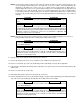
CAUTION ATTENTION In next step, ring gear (12), pinion (11) and key (13) will be removed. If ring (12) and pinion (11) are to be reused, identify them, with a marker or the like, so it can be determined to which housing they belong (if there is more than one housing in pump) and which direction face of each gear was positioned in housing. Do not mark with scribe or punch as this may leave a burr or high spot which could lead to pump damage or seizure.
NOTE: If round gear housing (3) will not slide easily off shaft (6) and this is the last round housing (3) to be removed, clamp round housing (3) in a vise with front cover (1) free. With a soft headed hammer, tap alternately on mounting ears of front cover (1) to separate it from round housing (3). When there is sufficient gap between front cover (1) and round housing (3), insert a wedging device. Pry gap until round housing (3) is free to slide off shaft (6).
15. Remove O-rings (40 and 80) from bearing housing (9). NOTE: If neither ball bearing (31) nor seal (51) are to be replaced or inspected, disassembly is complete. If either of these components are to be replaced or inspected for any reason, proceed as below. 16. Place inboard face of bearing housing (9) on the clean, smooth surface of an arbor press with coupling end facing up. 17. Remove socket head capscrews (75) and bearing retainer (70). 18. Remove ball bearing snap ring (33). 19.
3. RING GEAR OD – Light scratching and polishing is acceptable. If scoring is present, ring gear should be replaced. 4. HOUSING a. Faces – Some light scratching is acceptable, but if there is any scoring, the part should be replaced. b. Crescent – This piece should be checked for gouges or scoring. If the marking is severe, housing should be replaced. c. ID – If any scoring is present, housing should be replaced. 5.
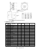
Figure 2 – Front Cover Figure 3 – Sleeve Bearing (53) Sizing Tool J. SPARE PARTS AND KITS IDP 1 3 4 6 8 9 11 12 13 15 31 32 33 34 35 36 37 38 39 40 41 42 51 53 70 74 75 80 81 * Qty.
K. REASSEMBLY OF PUMP CAUTION ATTENTION READ THIS ENTIRE PROCEDURE BEFORE ASSEMBLING PUMP NOTE: Inspect all running surfaces for scratching, scoring and wear prior to assembly of pump. Minor scratching is acceptable. If parts are heavily scratched or scored, they should be replaced. Thoroughly clean all pump components. WARNING Follow the supplier’s recommendations when using cleaning fluids.
CAUTION ATTENTION Take extreme care not to damage seal mating face or O-ring during assembly. Do not touch seal face with any tools. After installation, clean face with solvent and soft, lint free cloth. CAUTION ATTENTION If seal mating face is not bottomed out in bore of bearing housing (9), seal could be severely damaged. 5. Install ball bearing (31) into bearing housing (9) by hand. It should slide in easily.
17. Reinstall bearing retainer (70) onto bearing housing (9) with cap screws (75). Tighten capscrews with torque wrench per assembly drawing torque values. 18. Install first stage key (13), chamfer side up, into keyway of shaft (6) and push it up as far possible toward drive end of pump. NOTE: If key (13) has a step, install key (13) with step facing up and away from front cover (1).
27. Install second stage pinion gear (11) on shaft (6). Pinion gear (11) should slide freely on shaft (6) and key (13). If not, ensure key (13) is properly installed and shaft (6) and pinion (11) keyway are free of burrs. Ensure pinion (11) is installed in stage from which it was removed and is facing direction from which it was removed. CAUTION ATTENTION If gears are installed in wrong housing, pump may not perform properly or may seize during operation.
CAUTION ATTENTION If gears are installed in wrong housing, pump may not perform properly or may seize during operation. This is because gears are matched to each housing individually and may not have correct clearances if installed in another housing. If gears are installed facing wrong direction, pump may not perform properly or may seize during operation. This is because some gears have chamfers on only one side.
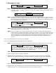
6 "X2" TORQUE TABLE FRAME SIZE BOLT SIZE PUMP MODIFICATION 2 M10 p 3 M12 4 M16 5 M20 6 8 TORQUE LB FT N.
Frame Bolt Pum Size Size Mod 6 "X1 and "X2" Torque lb-ft N.m w 2 M10 p 30±2 41 w 3 35 M12 p 60±5 M16 p M20 p 115 ± 10 156 M24 p 8 M30 p 90±5 122 237 175 ± 10 175 ± 10 237 175 ± 10 237 220 ± 15 298 220 ± 15 220 ± 15 298 870±25 1180 TORQUE TO 40 ±2 LB IN FOR SIZES 3, 4 & 5 TORQUE TO 15 ±2 LB FT FOR SIZE 6 3 INLET 122 61 650±20 881 650 ±20 881 650 ±20 881 870±25 1180 870 ±25 1180 870 ±25 1180 36 OUTLET 90±5 45 ±2 435 ± 15 590 (\.
Imo Pump 1710 Airport Road PO Box 5020 Monroe, NC USA 28111.5020 Tel: +1.704.289.6511 Toll: +1.877.853.7867 Email: cc@colfaxcorp.com W e b : c © 2012 Colfax Fluid Handling all rights reserved.