PRODUCT SERVICE MANUAL FOR CIG Mechanical Seal Triple Pumps WARNING The Imo General Installation Operation, Maintenance, and Troubleshooting Manual, (No. SRM00046), as well as all other component manuals supplied with these type units should be read thoroughly prior to pump installation, start-up, operation, maintenance or troubleshooting. SRM00052 REV.
READ THIS ENTIRE PAGE BEFORE PROCEEDING FOR THE SAFETY OF PERSONNEL AND TO PREVENT DAMAGE TO THE EQUIP- MENT, THE FOLLOWING NOMENCLATURE HAS BEEN USED IN THIS MANUAL: DANGER Failure to observe the precautions noted in this box can result in severe bodily injury or loss of life. WARNING Failure to observe the precautions noted in this box can cause injury to personnel by accidental contact with the equipment or liquids. Protection should be provided by the user to prevent accidental contact.
A. GENERAL INSTRUCTIONS The instructions found herein cover the disassembly, assembly and parts identification of CIG triple pumps. NOTE: Individual contracts may have specific provisions that vary from this manual. Should any questions arise which may not be answered by these instructions, refer to the General Installation Operation, Maintenance, and Troubleshooting Manual, (No. SRM00046), provided with your order.
. From the assembly drawing or instruction manual (see Table 1, Pump Parts List) provide the IDP number(s) and names for the replacement part(s). 5. Give the above information to your Imo service representative. Imo sales and service representatives are listed herein and in General Installation Operation, Maintenance, and Troubleshooting Manual, (No. SRM00046). F. OPERATION LIQUID LIMITATIONS Never operate with fluids that are corrosive to iron, steel, aluminum or bronze.
G. PUMP DISASSEMBLY Refer to Assembly Drawing In Back Of Manual CAUTION ATTENTION Read this entire procedure before disassembling pump. 1. Remove drive key (36). 2. Remove capscrews (42) and end cover (15) with O-ring (67). 3. Remove capscrews (17). 4. Remove back cover (63) from shaft (6). Do not permit dowel pin (22) to drop as back cover (63) is removed. Remove dowel pin (60 from either back cover (63) or square housing (62), whichever is applicable.
NOTE: If square gear housing (62) will not slide easily off shaft (6), clamp housing (7) in a vise with housing (62) free. Insert Prying device between the two housings and pry gap until housing (62) is free to slide off shaft (6). Remove and discard O-ring (40), if it did not come off with square housing (62). CAUTION ATTENTION Take care not to damage either faces that are being pried against or 0-ring (10) with prying device.
NOTE: If intermediate flange (5) will not slide easily off shaft (6), clamp square housing (4) in a vise with intermediate flange (5) free. Insert prying device between intermediate flange (5) and square housing (4). Pry gap until intermediate flange (5) is free to slide off shaft. CAUTION ATTENTION Take care not to damage either faces that are being pried against or 0-ring (41) with prying device.
17. Remove seal housing (9), with lip seals (32), from shaft (6). 18. If lip seals (32) are to be replaced, remove and discard them from seal housing (9).. 19. If ball bearing (31) is to be replaced, remove snap ring (33) from shaft (6), press ball bearing (31) off shaft (6) and discard. 20. If inside lip seal (51) is to be replaced remove and discard lip seal (51). H. INSPECTION OF PARTS 1. BALL BEARING – Ball bearings should be free turning and quiet.
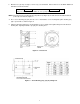
3. Machine face (A) deep enough to remove any scored material. Ensure that face is flat within .0008 inch TIR with a 32 microinch finish. CAUTION ATTENTION Being out of flat in excess of .0008" can cause pump failure. NOTE: If more than .015" is machined (removed) from face (A, Figure 2), the same amount should be machined (removed) from G and F, Figure 2. 4. Press sleeve bushing (53) (54) in front cover or intermediate cover ensuring that split in bushing (53) (54) is positioned as shown in Figure 2. 5.
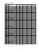
J. SPARE PARTS AND KITS IDP QTY DESCRIPTION Seal Kit Shaft Kit Front Pump Middle Pump Rear Pump Square Hsg. Square Hsg. Square Hsg. & Gear Set Kit* & Gear Set Kit* & Gear Set Kit 2 1 Front Flange 4 1 Front Pump Square Housing.
K. REASSEMBLY OF PUMP CAUTION ATTENTION READ THIS ENTIRE PROCEDURE BEFORE ASSEMBLING PUMP. NOTE: Inspect all running surfaces for scratching, scoring and wear prior to assembly of pump. Minor scratching is acceptable. If parts are heavily scratched or scored, they should be replaced. Thoroughly clean all pump components. WARNING Follow the supplier’s recommendations when using cleaning fluids.
7. Install O-ring (40) onto seal housing (9) rabbet. 8. Install seal housing (9) in front flange (2) and secure with cap screws (42). Torque capscrews, with torque wrench, to torque values on assembly drawing. 9. Install dowel pin (37) in front flange (2), if applicable. 10. Install O-ring (40) in face of front flange (2). 11. Install square housing (4) on shaft (6) and slide it up until it engages dowel pin (37) and counterbore in front flange (2) and is tight up against front flange face (2). 12.
18. Install square housing key (21), chamfer side up, into keyway of shaft (6). CAUTION ATTENTION If key (21) has a step, install key (21) with step facing up and away intermediate cover (5) face. CAUTION ATTENTION When key (21) is installed there must be an approximately .020" gap between it and intermediate cover (5) face.
26. Install key (66) chamfer side up in keyway of shaft (6) inside square housing (62) and push it up as far as possible toward drive end of pump. CAUTION ATTENTION If key (66) has a step, install key (66) with step facing up and toward drive end of pump. CAUTION ATTENTION When key (66) is installed there must be an approximately .020" gap between it and housing (62) face.
35. Install coupling key (36) in keyway of shaft (6). CAUTION ATTENTION Take care not to bump shaft during storage, transportation, or installation of pump into operating system. L. TROUBLESHOOTING For assistance with troubleshooting, see Imo General Installation Operation, Maintenance, and Troubleshooting Manual, (No. SRM00046).
14
Imo Pump 1710 Airport Road PO Box 5020 Monroe, NC USA 28111.5020 Tel: +1.704.289.6511 Toll: +1.877.853.7867 Email: cc@colfaxcorp.com Web: colfaxcorp.com © 2012 Colfax Fluid Handling all rights reserved.