PRODUCT SERVICE MANUAL FOR CIG Mechanical Seal Double Pumps WARNING The Imo General Installation Operation, Maintenance, and Troubleshooting Manual, (No. SRM00046), as well as all other component manuals supplied with these type units should be read thoroughly prior to pump installation, start-up, operation, maintenance or troubleshooting. SRM00051 REV.
READ THIS ENTIRE PAGE BEFORE PROCEEDING FOR THE SAFETY OF PERSONNEL AND TO PREVENT DAMAGE TO THE EQUIPMENT, THE FOLLOWING NOMENCLATURE HAS BEEN USED IN THIS MANUAL: DANGER Failure to observe the precautions noted in this box can result in severe bodily injury or loss of life. WARNING Failure to observe the precautions noted in this box can cause injury to personnel by accidental contact with the equipment or liquids. Protection should be provided by the user to prevent accidental contact.
A. GENERAL INSTRUCTIONS The instructions found herein cover the disassembly, assembly and parts identification of CIG mechanical seal double pumps. NOTE: Individual contracts may have specific provisions that vary from this manual. Should any questions arise which may not be answered by these instructions, refer to the Imo General Installation Operation, Maintenance, and Troubleshooting Manual, (No. SRM00046), provided with your order.
D. PUMP MODEL IDENTIFICATION This instruction manual covers the Imo CIG mechanical seal double pump design. The model of each pump is identified on the pump nameplate. Refer to Figure 1 for instructional keys when using this manual.
E. ORDERING INSTRUCTIONS When corresponding with Imo Pump regarding CIG Single Series pumps, refer to the pump nameplate, this instruction manual, and the assembly drawing as instructed below: 1. From pump nameplate, record the pump model number. Also record the manufactured lot number and date (these are stamped on the housing near the nameplate). 2. Record instruction manual number, revision and date. 3. From the instruction manual, record the figure numbers that apply to the replacement part(s) 4.
CAUTION ATTENTION Take care not to damage either faces that are being pried against or 0-ring (10) with prying device. CAUTION ATTENTION If gear housing (7) will not slide off easily because its bushing (53) was seized on shaft (6), ball bearing (31) was most likely damaged when housing (7) was pried off and must be replaced.
10. Remove O-ring (90) from front cover (1) if it did not come off with last housing removed. 11. Remove socket head capscrews (75) and bearing retainer (70) with lip seal (32), where applicable. 12. If lip seal (32) is included in the bearing retainer (70) and it is to be replaced, remove it from the bearing retainer (70) and discard. 13. Remove socket head capscrews (42). 14. Reinstall bearing retainer (70) and socket head capscrews (75). 15. Remove shaft (6) from front cover (1).
23. Loosen set screw and remove rotating part of mechanical seal (51) from shaft (006). CAUTION ATTENTION Take great care not to touch or damage the rotating face of the seal (051). This seal face is very sensitive to chipping and/or scratching. 24. Remove seal spacer (74) from shaft (6) if applicable. H. INSPECTION OF PARTS 1. BALL BEARING – Ball bearings should be free turning and quiet. Their grease should have a soft consistency and not look or smell burned. 2.
3. Machine face (A) deep enough to remove any scored material. Ensure that face is flat within .0008 inch TIR with a 32 micro inch finish. CAUTION ATTENTION Being out of flat in excess of .0008” can cause pump failure. NOTE: If more than .015” is machined (removed) from face (A, Figure 2), the same amount should be machined (removed) from G and F, Figure 2. 4.
J. SPARE PARTS AND KITS IDP Qty.
K. REASSEMBLY OF PUMP Refer To Assembly 1 CAUTION ATTENTION READ THIS ENTIRE PROCEDURE BEFORE ASSEMBLING PUMP. NOTE: Inspect all running surfaces for scratching, scoring and wear prior to assembly of pump. Minor scratching is acceptable. If parts are heavily scratched or scored, they should be replaced. Thoroughly clean all pump components.
CAUTION ATTENTION Take extreme care not to damage seal mating face or O-ring during assembly. Do not touch seal face with any tools. After installation, clean face with solvent and soft, lint free cloth. CAUTION ATTENTION If seal mating face is not bottomed out in bore of bearing housing (9), seal could be severely damaged. 5. Install ball bearing (31) into bearing housing (9) by hand. It should slide in easily.
17. Re-install bearing retainer (70) onto bearing housing (9) with cap screws (75). Tighten capscrews with torque wrench per assembly drawing torque values. 18. Install dowel pin (37) in front cover (1). 19. Install O-ring (90) in face of front cover (1). 20. Install square housing (4) on shaft (6) and slide it up until it engages dowel pin (37) and counterbore in front cover (1) and is tight up against front cover face (1). 21.
CAUTION ATTENTION If key (21) has a step, install key (21) with step facing up and away from back face of previous stage. CAUTION ATTENTION When key (21) is installed and pushed up toward drive end, there must be an approximately.020" gap between it and face of previous stage. If not, be sure previous stage is seated firmly up against face of last installed housing.
37. Install coupling key (36) in keyway of shaft (6). CAUTION ATTENTION Take care not to bump shaft during storage, transportation, or installation of pump into operating system. L. TROUBLESHOOTING For assistance with troubleshooting, see General Instruction Manual CA-1.
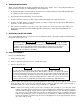
:31) (33) (70: 36: :3B}- TORQUE TO 40±2 LB IN "X2" TORQUE TABLE FRAME BOLT PUMP SIZE SIZE MODIFICATION :s3l (41) (12) (11) (53) (37) (1) (74) (9) (BO) r 17}- SEE TORQUE CHART OUTLET INLET I @TORQUE T040±2 LB IN FOR SIZES 3, 4 & 5 TORQUE TO 15±2 LB FT FOR SIZE 6 2 M10 3 I M12 4 M16 5 M20 6 M24 w p w p w p w p w p TORQUE LB FT N.
Imo Pump 1710 Airport Road PO Box 5020 Monroe, NC USA 28111.5020 Tel: +1.704.289.6511 Toll: +1.877.853.7867 Email: cc@colfaxcorp.com W e b : c colfaxcorp.com © 2012 Colfax Fluid Handling all rights reserved.