P.O.
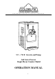
Foreword Thank you for selecting Coldelite to meet your operation and growing demands. Your Coldelite freezer has been manufactured utilizing the most advanced technology and modern equipment available in the industry. We at Coldelite, take great pride and care in the manufacturing of each and every freezer, using only the finest components available, to provide you with many years of trouble free operation.
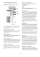
Foreword Part I Page # Installation A) Uncrating B) Positioning the Machine C) Electrical Requirements D) Completing the Installation Part II 7 7-8 8 Explanation of Controls A) Electronic Control Panel B) Dispensing Handle C) Photo Sensor Switch D) Dispensing Head Safety Switch E) Electric Control Panel F) Other Controls Part III 9-10 10 10 10 10-11 11 Initial Cleaning Procedure A) Gravity Fed Cleaning Procedure B) Pump Fed Cleaning Procedure C) Disassembling the Dispensing Head D) Disassembling the
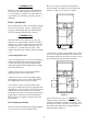
Prior to choosing a location keep in mind that the freezer should be accessible for periodic maintenance and have adequate space for necessary airflow. !! IMPORTANT !! Failure to closely follow operational and maintenance procedures may result in damage to the unit and / or void your warranty. Coldelite Corporation will not be responsible for any machine not properly operated or maintained.
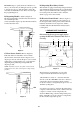
side bottom of the frame. The connection box is labeled “Connect Power Line Here”. Connect the power supply wires to the machines using the appropriate electrical hardware and strain relief devices. Note: If these clearances are not maintained, the production capacity will be reduced, cycling will be increased and the potential will exist that the machine will stop completely 3) It is necessary to clean the air condenser each month to remove dust, paper, etc., which may obstruct airflow.
Push to Select – Position 571.2 By pressing this button you can select any of the following machine modes: - Automatic - Stand-by - Beater The indicator light will illuminate corresponding to the mode selected with the touch pad. Part II – Explanation of Controls A) Electronic Touch Pad – (Refer to figure 4) 570 L1 Automatic Mode When placed in this mode the indicator light L2 will illuminate and the machine will start the freezing process in the cylinder.
DO NOT attempt to operate the freezer while low on mix or your freezer may be damaged. It is also possible to activate a beeper to sound when mix is low in the Automatic and Stand-By modes. This is done through the programming mode. D) Dispensing Head Safety Switch This machine is equipped with a dispensing head safety switch. With the dispensing head removed, the machine will not operate and Alarm 9 (AL9) will appear on the front touch pad monitor.
3) Beater Motor Overload Protector - Monitors the current draw of the beater drive motor. If the motor draws excessive amperage, the overload will trip and Alarm 1 (RtA) will be displayed on the touch pad monitor. 4) Main Transformer – This transformer reduces the incoming line voltage to 24 volts for the primary control circuit. 5) Electronic Control Board – This board controls and monitors ALL functions of the machine.
Next remove the outer regulating sleeve from the center tube by pulling straight off. Part III–Initial Cleaning Procedure !! IMPORTANT !! Before starting this procedure, place the machine in the STOP mode on the touch pad. This is a new machine and although clean, it must be completely disassembled, washed and sanitized before adding fresh product. Please proceed as follows: 1) Remove the mix tank cover and spare parts items packed inside the mix tank.
Disassemble the mix pump assembly as pictured below. When disassembling the orings from the other components, use only the oring removal tool provided in the spare parts tool kit. Using other tools to remove the orings from their grooves can result in damaging both the oring and component. B) Pump Fed Cleaning Procedure Proceed with the disassembly of the mix injection pump located in the mix storage tank. First slide the connecting tube forward away from the mix pump faceplate.
Pull the handle-retaining rod out far enough to allow the handle to disengage. C) Disassembling the Dispensing Head Loosen and remove the two dispensing head-retaining knobs. The knobs are removed by turning counter clockwise until loose. Return the retaining rod to its original position. Using the metal rod as a base, lever the piston from the dispensing head with the handle. Remove the dispensing head by pulling straight out and away from the machine.
Finally, remove the beater / auger end pusher by pulling straight out of the beater / auger frame. Remove the scraper blades from the beater / auger frame by gently rotating the blade out of the frame support brackets. D) Disassembling the Beater / Auger Remove the beater / auger assembly from the cylinder by pulling straight out of the machine towards you. The machine is now completely disassembled. The removed parts must now be washed, rinsed, and sanitized.
Install the idler into the beater frame by placing it through the end pusher. Part IV - Assembling the Freezer A) Assembling the Beater / Augers After completing the Cleaning Operation, you are now ready re-assemble the freezer. First locate the parts needed to assemble the beater / auger. A) End pusher, B) Beater frame, C) Idler, D) Beater seal, E) Scraper Blades (2per), F) Blade bumpers (2 per blade) NOTE: When installed correctly, the idler should rotate freely inside the beater frame.
Insert the beater assembly into the freezing cylinder. Holding the beater horizontal, gently slide it straight into the cylinder until it can go no farther. B) Assembling the Dispensing Head Locate the parts that will be needed to assemble the dispensing head. These parts include: A) Dispensing head oring, B) Dispensing head, C) Piston orings (2), D) Piston, G) Handle retaining rod, H) Dispensing handle, and I) Retaining rod oring.
Spread the lubricant to lightly coat the piston surface between and including the orings. This will ensure free movement of the pistons and dispensing handle. Insert the piston into the chamber of the dispensing head. When installing, align the square handle recess with the rectangular cut out of the head. Turn over the dispensing head and insert the two large orings into the grooves in the dispensing head. Lightly lubricate the outside of these orings.
Insert the splash guard into the top hole of the gravity feed tube. C) Assembling the Gravity Feed Tube Locate the parts needed to assemble the gravity feed tubes. This should include: A) Splash guard, B) Orings (2per), C) Outer regulating sleeve, D) Center gravity feed tube D B C A Lightly lubricate both orings on each tube with the sanitary lubricant. When finished, place a feed tube uninstalled at the bottom of each mix tank.
Install the two orings (#1126) into the bottom grooves of the feeding elbows (#32) then lightly lubricate. D) Assembling the Mix Injection Pump Before assembling the mix injection pump, locate all of the parts that will be required. (See Below) 207 1117 1197 39 248 105 1178 31 38A 202 1126 550 Install the assembled pressure relief plunger into the feed elbows, small end first. Next install the assembled connecting tube into the mix feed elbow, check valve first.
Install the mix pump drive shaft seal into the rear of the mix pump body. Lightly lubricate the inside of the shaft seal then install the drive shaft into the pump seal engaging it into the drive gear. Install the pump body assembly into the rear hub inside of each mix storage tank. Slide the drive shaft into the rear hub and rotate the pump until the hook stud engages the pin on the rear hub.
Part V - Sanitizing the Freezer Prior to filling the machine with fresh liquid mix, the assembled machine must be sanitized. The frequency of cleaning and sanitizing must comply with your local and / or state health regulations. If uncertain of these regulations, contact your local Health Departments or Department of Agriculture. Sanitizing your freezer is very important. This procedure will retard the growth of bacteria and insure excellent product bacteria test results performed by your local inspectors.
Press the “Stop – Reset” button (#571.1) and place the machine in the OFF / Stop mode. Allow the sanitizer to remain in contact with all of the product surfaces for 3 to 5 minutes. “Push to Select” button on the front touch pad (#571.2) until the beater mode is selected. Allow the machine to run in the beater mode for approximately 10 seconds then push the “Stop” button on the touch pad. This will remove any of the remaining sanitizer from the cylinder.
Part VI – Starting the Freezer Only after completing the cleaning and sanitizing procedures should you fill the machine with fresh mix. The mix being used MUST be free of ice, seeds, pulp, and completely dissolved if made from powder. The products used in these freezers must be a homogenous liquid. You may now start the freezing process by pressing the “Select” button (#571.2) and selecting the Automatic mode. 571.
With the mix tanks filled with liquid mix and the elbows connected to the pumps, you can now prime the cylinders. To prime the cylinders, press the “Select” button on the touch pad, selecting the “Beater” only mode. Allow the machine to run for approximately one minute the press the “Stop” button. B) Pump Fed Machines With your clean, sanitized hands, install the feeding elbow into the cylinder feed hole. Next slide the elbow connecting tube into the pump cover hole. 570 571.1 571.
Part VII – Operating the Freezer A) Stand-By Mode The machine will automatically stop the freezing process after achieving the pre-set “consistency” value (number displayed on the touch pad monitor). This will indicate that the product is ready to be served. At this time the compressor will continue to run and automatically switch to cooling the mix storage tanks. During long pauses between servings, press the “Push to Select” button (#571.2) and select the “Stand-By” mode of operation.
B) Gravity Fed Machines C) Pump Fed Machines-Operation The gravity feed tube consists of two tubes, one sliding inside of the other, and a center splash guard. The inner tube blends the flow of air and mix into the freezing cylinder. Air enters through the top of the tube, mix through the bottom. (Refer to figure 9) The mix injection pump runs whenever the beater drive motor is turning.
Part VIII – Periodic Cleaning Procedures With the machine still in the Beater mode, place a pail under the dispensing head. Slowly pull the handle and allow all of the product to drain from the machine. Cleaning and sanitizing schedules for your freezer are determined by your local Health Department and / or Department of Agriculture and must be followed accordingly. Check with your local organization prior to determining your cleaning schedule.
Drain the remaining water and soap solution from the freezer. B) Pump Fed Machines With frozen mix in the cylinder, select the Beater mode on the front touch pad by pressing the Push to Select button (#571.2) until pilot light #L4 illuminates. Allow the machine to operate in the beater mode for 4 to 5 minutes. This will soften the product and allow for easier product removal. 571.
Remove the feeding elbow assembly from the mix tank by first sliding the connecting tube away from the pump cover, Then turn the elbow assembly slightly and pull the assembly straight up and out of the mix tank. Press the Push to Select button on the front touch pad (#571.2), and carefully select the Beater mode. Allow the machine to run for 1 – 2 minutes then push the Stop / Reset button (#571.1) on the touch pad. Drain all of the water and soap solution from the machine.
You are now ready to disassemble and clean your freezer. Please refer to Part III – Initial Cleaning Procedure of this operation manual for instructions on how to proceed. D) The sensitivity of this switch can be adjusted with a small screwdriver. The trimmer location is on the switch body nearest the front panel. To adjust, the adjustment screw should be turned very carefully either in a clockwise direction to increase the range or counter clockwise to decrease the range of operation.
Part X – Maintenance Your Coldelite freezer has been designed, engineered, and manufactured to achieve high performance and long durability. The life expectancy of any machine depends not only on the quality of engineering, and components used, but also on the basic maintenance procedures. It is important for you to become familiar with a few of the basic operating procedures. • Only remove orings with the oring extractor provided in the machine spare parts kit.
A) Trouble Shooting Guide – Gravity Fed Freezers Problem Possible Cause Suggested Solution 1) Product too soft a) Drawing faster than the machine can produce b) H.O.T. control set too low for product c) Low on refrigerant a) Slow down draw rate b) Set H.O.T.
A.1) Trouble Shooting Guide – Pump Fed Freezers Problem Possible Cause Suggested Solution 1) Product too soft a) Drawing faster than the machine can produce b) Suction tube setting too large for draw rate c) H.O.T. control set too low for product d) Low on refrigerant a) Slow down draw rate b) Reset the suction tube to a smaller orifice setting (rotate CCW) c) Set H.O.T.
B) Machine Safety Alarms This freezer is equipped with built in, self monitoring (Safety) devices, which will interrupt operation of the freezer if activated. When activated, the little red LED light at the bottom right corner of the display monitor will illuminate and flash. (refer to Figure 12) This LED will flash when the alarm has been activated. It will stop flashing, but remain lit when the machine has reset and resumed operation. To deactivate the LED, press the Stop / Reset button on the touch pad.