User Guide (Ver.1.7) Model: DVR82HD 2 Channel HDcctv + 8 Channel Full D1 Digital Video Recorder About This User’s Guide Before operating the unit, please read this user‟s guide thoroughly and retain it for future reference.
Cautions Explanation of Graphical Symbols This symbol indicates the presence of important operating and maintenance (servicing) instructions in the literature accompanying the product. This symbol indicates the presence of “dangerous voltage” within the product’s enclosure that may be of sufficient magnitude to constitute a risk of electric shock, property damage, personal injury, or death. WARNING To reduce a risk of fire or electric shock, do not expose this product to rain or moisture.
These precautions must be followed for safety reasons. Warning Do not use if the unit emits smoke. Do not disassemble the unit. Do not place any heavy or sharp objects on the unit. Do not place on uneven surface. Do not expose to shock or vibration. Do not move the unit when the unit is powered on. Do not block, and allow dust to accumulate in the air vents. Do not restrict airflow of the unit; doing so can damage the unit.
Product Components Please make sure the following components are included as specified below. DVR Unit Client Software CD Remote Control Battery1.
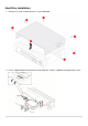
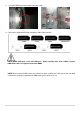
Hard Drive Installation 1. Remove the screws and the top cover as specified below. 2. Fix the supplied HDD mounting bracket to the hard disk using the supplied mounting bracket screws.
3. Insert the HDD bracket to the hole and fix the screw. 4. Connect the supplied SATA cable and power cable to the hard disk. NOTE) HDD2 SATA port is the main HDD port. When installing more than 2 HDDs, connect HDD SATA cables in sequential order from HDD2. NOTE) Please mount all HDDs which you want to use when installing at the first time. It does not allow a movement, removal or supplement of HDD to the system which be in use.
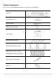
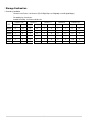
Storage Estimation Recording Condition - Channel and Frame: 10 Channels (Full-HD@15fps or HD@30fps and D1@30/25fps) - Recording by: Continuous - Audio Recording: 10 Channel Audio On LEVEL 5(H) LEVEL 4 LEVEL 3 LEVEL 2 LEVEL 1(L) HDD day(s) hour(s) day(s) hour(s) day(s) hour(s) day(s) hour(s) day(s) hour(s) 250GB 0 15 0 19 1 2 1 7 1 14 320GB 0 20 1 1 1 10 1 16 2 2 500GB 1 9 1 17 2 6 2 17 3 8 1TB 2 19 3 12 4 15 5 12 6 20 1.
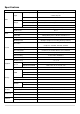
Specifications Model DVR82HD Channel Input Level 2 CH HDcctv 720p / 1080p 8 CH Composite Input Video Loss Check Video Output YES Main Monitor Output 1 HDMI (Max. 1920x1080p60 and Various Resolution) Sub Monitor Output 1 VGA (Max. 1920x1080p60 and Various Resolution) CVBS and Spot Audio 1 CVBS , 4 SPOT OUT Input and Output 10 CH Input & 1 CH Output Audio Codec G.711 Sensor Input 10 TTL, NC/NO Selectable Alarm Alarm Out 4 Relay Out by Sensor, Motion and Video Loss Compression H.
Network Interface 10/100/1000 Base TX Ethernet (RJ45 1EA) Dual Network Streaming 2 CH HDcctv: H.
Table of Contents 1. Main Features ............................................................................................................................. 13 2. Booting the System and Initial Setting ......................................................................................... 14 2-1. Booting the DVR and Basic Time Setting...................................................................................... 14 2-2. Setting Daylight Saving Time ..........................................
5-3-6. Archive Search .......................................................................................................................... 52 5-3-7. Log Search ................................................................................................................................ 52 5-4. Play Mode .................................................................................................................................... 53 6. PTZ Control ...............................................
10-1. 3G App Viewer for iPhone .......................................................................................................... 89 10-2. 3G App Viewer for Android Phone .............................................................................................. 91 APPENDIX: Network Connection - LAN ............................................................................................. 93 APPENDIX: Network Connection – Internet and DDNS ......................................................
1. Main Features HDcctv Compatible 2 channel HDcctv and 8 channel analog full D1 Easy Record, Copy and Setup Recording Rate: 120fps @ 720p HDcctv resolution H.264 high quality compression saves HDD space Simultaneous live view/playback while continuing to record/network transfer or backup Remote monitoring/recording/playback/configuration and control via internet 4 Channel Audio Recording NOTE: Under federal law, The Fourth Amendment to the U.S.
2. Booting the System and Initial Setting 2-1. Booting the DVR and Basic Time Setting 1. During the first start up, the following logo and message will be displayed. 2. After the system initializing is completed, select the language and set date and time as specified below.
2-2. Setting Daylight Saving Time To enable Daylight Saving feature/NTP synchronization, take the following steps. 1. Enter the SETUP mode. The default Password is “1111”. 2. Go to SETUP>SYSTEM>SET DATE & TIME 3. Select ON from the DAYLIGHT SAVING dropdown menu.
2-3. Setting NTP (Network Time Protocol) 1. When the DVR is connected with internet and the DVR need to be syncronized with NTP (Network Time Protocol), set SETUP>SYSTEM>NTP ON. 2. Select proper TIME ZONE time. Table2.3.1.
AR Arkansas GMT-6 GMT-5 CA California GMT-8 GMT-7 CO Colorado GMT-7 GMT-6 CT Connecticut GMT-5 GMT-4 DC District of Columbia GMT-5 GMT-4 DE Delaware GMT-5 GMT-4 FL Florida GMT-5 GMT-4 FL Florida (W) GMT-6 GMT-5 GA Georgia GMT-5 GMT-4 HI Hawaii GMT-10 NA ID Idaho (N) GMT-8 GMT-7 ID Idaho (S) GMT-7 GMT-6 IL Illinois GMT-6 GMT-5 IN Indiana GMT-5 GMT-4 IN Indiana (SW / NW) GMT-6 GMT-5 IA Iowa GMT-6 GMT-5 KS Kansas GMT-6 GMT-5 KS Kansas (W) GM
OH Ohio GMT-5 GMT-4 OK Oklahoma GMT-6 GMT-5 OR Oregon GMT-8 GMT-7 OR Oregon (E) GMT-7 GMT-6 PA Pennsylvania GMT-5 GMT-4 RI Rhode Island GMT-5 GMT-4 SC South Carolina GMT-5 GMT-4 SD South Dakota (E) GMT-6 GMT-5 SD South Dakota (W) GMT-7 GMT-6 TN Tennessee (E) GMT-5 GMT-4 TN Tennessee (W) GMT-6 GMT-5 TX Texas GMT-6 GMT-5 TX Texas (W) GMT-7 GMT-6 UT Utah GMT-7 GMT-6 VT Vermont GMT-5 GMT-4 VA Virginia GMT-5 GMT-4 WA Washington GMT-8 GMT-7 WV W
3. Name, Function and Connection 3-1. Front Panel The following information will help you to operate the front panel controls. Figure 3.1.1. Front Panel Table 3.1.1. Indication Lamps Name CH1~10 HDD RECORD ALARM NETWORK BACKUP Description Indicating that the channel is being recorded. Indicating that the system is accessing the hard disk. Indicating that the system is recording video data. Indicating that when sensor(s) is/are triggered or motion is detected.
SEARCH Press to go to SEARCH menu in live display mode. Press to move left or to change the values in Setup mode. It is also used as the number 4 when entering password. Press to move up the menu in Setup mode. It is also used as the number 1 when entering password. Press to move right or to change the values in Setup mode. It is also used as the number 2 when entering password. Press to move down the menu in Setup mode. It is also used as the number 3 when entering password.
6 VGA Connector for VGA monitor. 7 HDMI OUT Main Video Output 8 USB Port Connector for Mouse or Backup 9 RS-232 10 ETHERNET 11 E-SATA POS Interface (TBD). RJ-45 connector for network function 2 e-SATA ports to archive still-image or video into a External Storage HDD . RAID Units to be available in the future RS-485 termination switch for 1st and 2nd. 12 TERMINATE 13 POWER SOCKET Connect for AC110V~250V 14 RS-485 1st and 2nd ports for RS-485.
4. Setting up the DVR The following sections detail the initial setup of the DVR. Menu screen will close if user input is not received in 5 minutes. 4-1. Setup – Main Live Screen To enter the setup menu, click on the mouse right button and select setup from the submenu or press the setup button on the front panel or the remote control. Table 4.1.1. Setup Menu Tree When the DVR prompts the LOG-IN window, enter the PASSWORD using the virtual keyboard, or the front panel, or the remote control.
4-2. Setup – DISPLAY In the SETUP menu, select the DISPLAY tab. Then, the DISPLAY menu is displayed as pictured below. Navigate through the menu items using the mouse or the control button on the remote control and change the value of the menu item. To return to the previous setup menu screen, press the ESC button. Figure 4.2.1. Display Mode Setup Screen Table 4.2.1. Menu Items in DISPLAY Mode Setup Item OSD Description Enable/disable on-screen-display.
COVERT Enable/disable display of the video channel in live display mode. BRIGHTNESS Change the brightness value of the specified channel.(0-100) It is for analog channels (1~8ch) only and is not for HDcctv channels (9,10ch). CONTRAST Change the contrast value of the specified channel. (0-100) It is for analog channels (1~8ch) only and is not for HDcctv channels (9,10ch). HUE Change the hue value of the specified channel.
4-3. Setup – RECORD In the SETUP menu, select the RECORD tab. Then, the RECORD menu is displayed as pictured below. Navigate through the menu items using the mouse or the control button on the remote control and change the value of the menu item. Figure 4.3.1. Recording Mode Setup Screen Table 4.3.1. Menu Items in Recording Mode Setup Menu Item CHANNEL Description Select a channel for applying the following settings using the mouse or the control button on the remote control.
QUALITY Select the recording quality for the specified channel. Options are; Level 1 (Low), Level 2, Level 3, Level 4, and Level 5 (High) RECORDING Assign the recording mode for each channel. Options are: Continuous, Motion, Sensor, Schedule or Disable. SENSOR Enable setting up to 4 sensors for the specified channel using the mouse or the RECORDING control button of the remote control. PRE RECORD Enable/disable pre-event recording.
4-3-1. Recording Schedules To setup a recording schedule, select SCHEDULE in the RECORD menu. Navigate through the items using the mouse or the control button. Select CHANNEL > select NONE, CONTINUOUS or MOTION > HIGHLIGHT AREA To copy a schedule to a different channel, select the channel from the COPY SCHEDULE menu. . Figure 4.3.2.
4-4. Setup – DEVICE In the SETUP menu, select the DEVICE tab. Then, the device menu is displayed as pictured below. Navigate through the menu items using the mouse or the control button on the remote control and change the value of the menu item. Figure 4.4.1. Device Mode Setup Screen Table 4.4.1. Menu Items in Device Setup Screen Item ALARM OUT Description Set the sensor, motion, and video loss for triggering alarm relay. HDD Error and Video Loss can trigger beeping.
2. Press the same number as ID set in DVR on the remote control. 3. An icon will be displayed on the Live Screen that corresponds to the remote control ID number.0 The options are from 0 to 99 SENSOR Select sensor from 1 to 10. TYPE Set the type of sensor for the specified channel. Options are: OFF, NORMAL OPEN, and NORMAL CLOSE. 4-4-1. ALARM-OUT Figure 4.4.2. ALARM-OUT Setup Screen Table 4.4.2. Menu Item in ALARM-OUT Setup Screen Item Description ALARM OUT Select an Alarm out number.
4-4-2. Controller & PTZ Setup Figure 4.4.3. Controller & PTZ Control Setup Screen Table 4.4.3. Menu Item in Controller & PTZ Control Setup Screen Item Description CHANNEL Select Channel number that the PTZ is connected to CAMERA Select the protocol type of the PTZ camera that is connected.
4-4-3. Spot Out Figure 4.4.4. SPOT-OUT Setup Screen Table 4.4.4. Menu Item in SPOT-OUT Setup Screen Item SPOT OUT Description Spot Out 1: from 1 channel to 4 channel Spot Out 2: from 5 channel to 8 channel Spot Out 3: for 9 channel Spot Out 4: for 10 channel SPOT TYPE Select Full screen or Quad screen mode. SPOT ON EVENT Enable/Disable display of the channel when an event is active. SPOT EVENT Set the dwell time for the display of the event activated channel.
4-4-4. Motion Zone Setup Select MOTION ZONE using the mouse or the control button on the remote control and select either PARTIAL ZONE or FULL ZONE using the mouse control. The default value is FULL ZONE. If FULL ZONE is selected, the motion zone grid screen is not displayed. Only set the level of sensitivity for MOTION SENSITIVITY. FULL ZONE: The motion sensor is active on the whole screen. PARTIAL ZONE: The motion sensor is active in the set detection frame.
4-5. Setup – STORAGE In the SETUP menu, select the STORAGE tab. Then, the STORAGE menu is displayed as pictured below. Navigate through the menu items using the mouse or the control button on the remote control and change the value of the menu item. Figure 4.5.1. STORAGE Setup Screen Table 4.5.1. Menu Items in STORAGE Setup Screen Item OVERWRITE Description When enabled, the DVR will continue recording and overwrite the oldest existing recorded data once the hard drive is full.
DISK INFO Hard drive information. Displays the following information; RECORDING - HDD Size - HDD Start Time and HDD Last Time - Model name - Temperature - Power on time - HDD Health status Enable/disable recording limit. LIMIT RECORDING Set the recording limit days. (1- 90 days) LIMIT DAYS If the RECORDING LIMIT DAYS is set to 1, the data will be overwritten after 24 hours. S.M.A.R.T Set the alarm and beep by setting the HDD temperature limit.
4-6. Setup – SYSTEM In the SETUP menu, select the SYSTEM tab. Then, the SYSTEM menu is displayed as pictured below. Navigate through the menu items using the mouse or the control button on the remote control and change the value of the menu item. Figure 4.6.1. SYSTEM Setup Screen Table 4.6.1. Menu Items in SYSTEM Setup Screen Item DVR ID Description Set DVR ID using the mouse or the control button on the remote control. Press OK to apply the DVR ID.
LANGUAGE Select the display language using the mouse or the control button on the remote control. Once a language is selected, the display language changes. DATE Select the date display format using the mouse or the control button on the remote FORMAT control.
NTP NTP is an abbreviation for Network Time Protocol, which is for synchronizing the time of the computer systems over variable-latency data networks. PRIMARY SNTP SERVER: Input the address of the primary NTP time server. SECONDARY SNTP SERVER: Input the address of the secondary NTP time server. TIME ZONE: Greenwich Mean Time (GMT) is a term originally referring to mean solar time at the Royal Observatory, Greenwich, London.
4-7. Setup – SECURITY In the SETUP menu, select the SECURITY tab. Then, the SECURITY menu is displayed as pictured below. Navigate through the menu items using the mouse or the control button on the remote control and change the value of the menu item. Figure 4.7.1. SECURITY Setup Screen Table 4.7.1. Menu Items in PASSWRORD Setup Screen Item USER Description Only the Admin will have access to the menu.
ADMIN, NETOWRK, USER1, USER2, USER3: Selected Checkbox: The user can access to the function. Blank Checkbox: The user can not access to the function. USER Options are ADMIN, NETWORK, USER1, USER2 and USER3. PASSWORD Select USER PASSWORD using the mouse or the control button on the remote control and press SEL button. Select user type and enter the current password. And, enter a new password, enter the same password again to confirm and select OK. Then the message “PASSWORD CHANGED” is displayed.
4-8. Setup – NETWORK Select the NETWORK tab. Then, the network menu is displayed as pictured below. Navigate through the menu items using the mouse or the control button on the remote control and change the value of the menu. Figure 4.8.1. NETWORK Setup Screen Table 4.8.1. Menu Items in Network Setup Screen Item Description PORT Port number (Default: 5445) WEB PORT Web Sever Port number (Default: 80) NETWORK TYPE DHCP: DVR will automatically retrieve an IP address from the network.
4-8-1. Network Types 4-8-1-1. DHCP An IP address is automatically assigned by the DHCP server, which automatically assigns the IP address and other parameters to new devices. ADSL and other network types that use a variable IP address method uses this process to acquire an IP address. 4-8-1-2. STATIC Figure 4.8.1. Network Setup Screen – STATIC IP address, Subnet Mask, Gateway, and DNS are manually assigned by the user. IP ADDRESS: The fixed IP address of the DVR unit.
4-8-2. DDNS Dynamic Domain Name System (DDNS) allows a DNS name to be constantly synchronized with a dynamic IP address. It allows those using a dynamic IP address to be associated with a static domain name. Once the setting is completed, the DDNS address will be: http://hostname.ddns.specoddns.net For example, if you enter the host name as “SPECOHD”, then the address will be: http://specohd.ddns.specoddns.net Select NETWORK>DDNS. The menu displays as below. Figure 4.8.2.
4-8-3. Network Port and Web Port Connecting DVR/DVRs through an IP sharing device, each DVR must be assigned a unique TCP port number for access from outside the LAN. This port number is displayed on NETWORK>NETWORK PORT Setup MENU. NOTE If you access the DVR only within the same LAN, the TCP port number does not need to be changed.
4-9. Setup - CONFIG In the SETUP menu, select the CONFIG tab. Then, the configuration menu is displayed as pictured below. Navigate through the menu items using the mouse or the control button on the remote control and change the value of the menu item. Figure 4.9.1. Configuration Setup Screen Table 4.9.1. Configuration Setup Item Description SAVE SETUP User can save the current configuration (Setting values) of the DVR to the USB TO A USB flash drive.
LOAD Press the button to reset the system to the default settings. DEFAULT The following settings such as Language, DVR ID, Security User Authentication, Security User P/W, Date format, DLS settings, Network settings, HDD overwrite, Limit recording, HDD serial number, and HDD ERROR time will not be included. LOAD Press the button to reset the system to the factory default settings.
5. Live, Search and Playback 5-1. Live 5-1-1. Main Live Screen and Icon In the Live screen, video inputs from the cameras are displayed as they are configured in the Display Setup screen. Various On-Screen Display (OSD) symbols, which indicate the status of the DVR, are described in Table 5.1.1. Figure 5.1.1. Live Viewing Screen Table 5.1.1. Status Indicator Icons in Live Viewing Screen Icon Description Indicates that the lock is set. Audio mute.
Event indicator. When there is an event (motion recording, video loss, HDD fail, S.M.A.R.T), this icon will be highlighted bright. Indicates that a network client is connected to the DVR. Indicates that sequencing mode is enabled. Displays the current date and time. RC: ALL Remote control ID display. If a remote ID is not set, the message “ALL” is displayed. Displays the amount of recording on the hard disk from 0-99%. Indicates that HDD is recycled. Continuous recording in progress.
Table 5.1.2. Quick Operation Window Icon Description SETUP Setup button. Click this button to go to a setup menu. AUDIO Audio button. Click this button to set an audio reception type; Audio Mute, 1 channel or 4 channels. To set just 1 channel, select a specific channel on the live screen at first. SEARCH Search button. Click this button to enter the search menu. BACKUP Backup button. Click this button to do a back-up. CAMERA PTZ Camera PTZ button. Opens the PTZ control menu.
5-2. Digital Zoom in Live and Playback Screen DVR4HD supports Digital Zoom feature during live and playback mode. 1. Double click the target channel. 2. Click the left button of the mouse and drag to make rectangular shape. 5-3. SEARCH Screen To enter the search screen menu, select SEARCH menu on the screen using the mouse or press SEARCH icon on live screen. Figure 5.3.1.
5-3-1. TIME-LINE Search The TIME-LINE search window is used to find the stored video by using the time line bar. Figure 5.3.2. Calendar Screen Figure 5.3.3. Time-Line Search Screen When the Timeline menu is selected, the user can see a calendar which has the recorded data. Select a specific date and time. Use a drag-and-drop function of the mouse control. User can select a specific minutes using a button in the above red box. Press the PLAY button after selecting the specific time.
5-3-2. Event Search The Event Search window is used to find stored video. Figure 5.3.4. Event Search Screen When the Event menu is selected, the user can see a calendar which has recorded data. Select a specific date and the event log will be displayed. Press the PLAY button to playback the data or the SAVE button to save the data after selecting the specific data. User can find a data of the specific channel and event using a button in the above red box. Press the PREV to return to the SEARCH window.
5-3-6. Archive Search The ARCHIVE Search window is used to find previously stored video or images. Figure 5.3.5. Archive Search Screen When the Archive menu is selected, the user can see a calendar which has recording data. Select a specific date and then the archived data will be displayed. Press the Display button to view the still image or the first frame of the selected video, then the user can save the selected data. 5-3-7.
5-4. Play Mode During playback of a recorded event, the mode changes from SEARCH to PLAY. While in PLAY mode, you may return to the SEARCH screen by pressing the X button on the status bar or the ESC button of a remote control. Figure 5.4.1. Play Mode Screen The following status bar hides automatically and appears again when putting a mouse pointer to the bar. Table 5.4.1. Button Functions in PLAY Mode Button Description Return to the previous menu screen, search window, or exit from the Menu.
6. PTZ Control To control the PTZ functions of the camera, select PTZ menu on the screen using the mouse. Select the item you wish to control the PTZ camera and control them using the mouse or the control button on the remote control. Table 6.1. Button Functions in PTZ Control Item Figure 6.1. PTZ Description INITIALIZE Initialize the PTZ settings of the selected camera. PAN / TILT Select PAN/TILT using the mouse or the control button Control Screen and press SEL button on the remote control.
7. Back Up 7-1. Still Image Backup onto USB Flash Drive Still images can be captured and archived onto a USB flash drive or an external hard drive in live mode or while playing back recorded video. In the live mode, press the BACKUP button to launch the archive function or select BACK UP menu on the screen using the mouse. 1. Select a specific channel which wants to backup on live screen. 2. When you press BACKUP button, the archiving screen will display as Figure 6.1.1. 3.
Figure 7.2.1. Video Archiving and Backup Screen 7-3. Transferring Still Images or Video from the ARCHIVE List The stored data in the hard drive can be found in the ARCHIVE list in the SEARCH window. User can back up still images or video into the storage device from the ARCHIVE list. 1. Select the date to begin searching and navigate through the days using the mouse or the control button or the remote control. 2. Once you have selected the date, press the NEXT button to open the list of stored data. 3.
Figure 7.3.1. Archive Search Screen 7-4. Playback of Backup Video H.264 format video can be played back using the player that the DVR copies on USB flash drive with video. Digital Zoon Feature: Use the mouse scroll to use digital zoom in and out feature.
Figure 7.4.1.
8. Network Access Using of SpecoTech Multi Client 8-1. Overview The SpecoTech Multi Client is a multiple site monitoring client software with; video, audio, and alarm signals from the DVRs over networks. The SpecoTech Multi Client does not limit the number of DVR units to register. The program displays up to 16 DVRs and supports dual monitors. On the program, user may control PTZF cameras on the DVRs.
8-3. Installation of the Program 1. Insert the provided CD in the CD drive and double-click “SpecoTech Multi Client (XXXX).exe” 2. Select a destination folder and click “Next”. 3. Select the program folder and click “Next”. 4. The installation status screen is displayed. 5. After the installation is completed, “SpecoTech Multi Client” icon displays on the desktop screen.
8-4. Live Window When installation is completed, double click the “SpecoTech Multi Client” icon on your desktop to start the program. 8-4-1. Main User Interface 8-4-2. Control Buttons Button Description Click this icon to run a playback window to search and play videos that LOCAL PLAYBACK are recorded in the local PC. Click this icon to run a playback window to search and play videos that REMOTE PLAYBACK are recorded in the remote DVR.
THUMBNAIL REFRESH: Click this icon to refresh and renew thumbnail image of the connected sites. SITE ADDITION: Click this icon to open „Site Addition‟ window. SITE DELETE: Click this icon to delete site from the index window, SITE MANAGEMENT after disconnect a site. NET FINDER: Select the site from the index window and click this icon to modify the information of specific site. CONNECT DISCONNECT Click this icon to connect the selected site/sites. Click this icon to disconnect the selected site/sites.
8-5. Search and Playback Window 8-5-1. Main User Interface You can access to search window by clicking the search icon (Local Playback / Remote Playback) on the upper left of the Live Window. 8-5-2. Main Control Panel Button Description Click this icon to run a playback window to search and play videos that LOCAL PLAYBACK are recorded in the local PC. Click this icon to run a playback window to search and play videos that REMOTE PLAYBACK are recorded in the remote DVR.
THUMBNAIL REFRESH: Click this icon to refresh and renew thumbnail image of the connected sites. SITE ADDITION: Click this icon to open „Site Addition‟ window. SITE DELETE: Click this icon to delete site from the index window, after disconnect a site. NET FINDER: Select the site from the index window and click this icon to modify the information of specific site. CONNECT Click this icon to connect the selected site/sites. DISCONNECT Click this icon to disconnect the selected site/sites.
To display the recorded data of selected channel or all channels on a time line scale. To change a timeline scale from 24 hours to 60 minutes. The timeline shows recorded data in color on the bar. You can adjust the timeline scale and move it to the time you wish to playback. Then click the play icon to display the recorded video. Playback buttons. Digital Zoom Window in Live and Playback.
8-6. Setup of SpecoTech Multi Client Click the setup icon to setup the configuration of UMS Multi Client software. The SETUP window is displayed as below. 8-6-1. General Security Option: Set a password for security options. Select security options and set a password. Then when you access any of selected functions, you need to enter the password. You can also set the save path for capturing and backup Save Path: Specify the location to save captured still image for Capture and Backup data.
8-6-2. Event Event log can be archived and searched. Event Log: Specify the location to save event logs and select event to archive. Event Search: Event log can be searched from selected time.
8-6-3. Record Record Setup: You can set the recording conditions as the following; Always, Event, or Auto record. And you can also select target DVR/DVRs and channel/channels. When you set the recording condition to event, you can set event for motion or alarm with duration. Record Local Storage Setup: You can select the local disk to record and the amount of disk space you want to allow the program to use for recording.
8-6-4. Display You can select the OSD (On Screen Display) to be displayed. 8-6-5. About English, French and Spanish is selectable.
8-7. Remote Setup The menu settings for the DVR unit can be set over network. Put the cursor of the mouse on the channel which is connected to the site and right click on the mouse to open the submenu. Then the following window is displayed as below. Select the REMOTE SETUP. Then the setup window is displayed. The specified menu screen is displayed on the upper left of the screen. Enter the password of the DVR when prompted.
8-7-1. Display Select the DISPLAY tab to set the DISPLAY conditions. These settings apply to all channels. OSD: Sets whether to display or not date and time as well as channel number on the screen. OSD Contrast: Adjust the character contrast on the screen. Sequence: Setting for automatically switching the displayed video. Sequence-Dwell Time: Sets the interval for automatically switching the screens. These settings apply to the specified channel only. Channel designation Name: Sets a channel name.
8-7-2. Record Select RECORD tab to set the recording conditions. These settings apply to the specified channel only. Channel Designation Resolution: Sets the resolution for the recordings. The set value applies to an individual channel. Frame Rate: Sets the recording rate. Quality: Sets the image quality in 5 levels. Recording: Sets the recording mode. Sensor Recording: Sensor recording is performed when an external sensor signal is input to the specified external sensor input terminal.
8-7-3. Device Select Device to set the motion zone, sensor input/alarm output conditions, PTZ control and spot setting conditions. Alarm Output: Sets the alarm output conditions. Alarm out No.: Specifies the alarm output terminal number (1~4) Sensor In: Outputs an alarm signal when the specified sensor terminal receives an input. Motion On: Outputs an alarm signal when the specified video input receives a motion detection.
8-7-4. Storage Select Storage to configure continued recording settings by overwriting the hard disk and the storage period for the recording data. Overwrite: To continue recording by overwriting when the hard disk becomes full, check the checkbox. Record Limit: Sets whether to limit or not the recording data storage period. Record Limit Days: Sets a recording data storage period. S.M.A.R.T.: Sets the TEMPERATURE LIMIT of the Hard Disk to trigger the ALARM and the BUZZER.
8-7-5. System Select System to set system and time settings. DVR ID: Sets individual designation to DVRs. Date Format: Select the date display format YYYY/MM/DD, MM/DD/YYYY, DD/MM/YYYY, YYYY-MM-DD,MM-DD-YYYY, DD-MM-YYYY NTP: Sets whether to synchronize the time using NTP server or not. Primary SNTP Server: Input the NTP primary server address. Secondary SNTP Server: Input the NTP secondary server address. Time Zone: Select the time zone. Connection Mode: Select the connection mode to NTP time server.
8-7-6. Network Port: When connecting multiple DVRs to the network, set a unique port number to each DVR. Web Port: Set a web server port number. Network Type STATIC: The address setting mode is manual. Input IP, Gateway, Subnet Mask, and DNS server IP. DHCP: The address setting mode is automatic. Addresses and other information do not need to be set. DDNS: Set whether to use DDNS service or not. Network Stream: Set the Resolution, Frame Rate, and the Quality.
8-7-7. Remote Upgrade Browse: Select BROWSE to locate the firmware file. Upgrade: Select UPGRADE to upgrade the firmware of the DVR.
8-8. Operation 8-8-1. Addition, Delete, and Modify of DVR Sites 8-8-1-1. Addition of Sites 1. Click SITE ADDITION button. And then the following window will be displayed as below. o Site Name: Input a name that properly describes a site. o IP Address: Input IP address (Public IP address of a router that DVR is connected.) or Domain name o Port Number. Default Port Number is “5445”. o ID: Input ID of DVR. Default ID is “admin”. o Password: Input network password of DVR. Default Password is “1111”.
8-8-1-3. Modify of Sites 1. Select the site/sites to modify from the directory window. 2. Click NET FINDER button. And then the following window will be displayed as below. 3. Click MODIFY button. And then the modified information is applied.
8-8-2. Connect and Disconnect 8-8-2-1. Connect 1. Select site/sites to connect from the directory window. 2. Click CONNECT button, and then site/sites displays/display as connected. 8-8-2-2. Disconnect 1. Select site/sites to disconnect from the directory window. 2. Click DISCONNECT button, and then selected site/sites disconnected.
8-8-3. Still-image Capture during Live 1. Double-click a channel to capture from the display screen. (Otherwise all channels will be captured.). 2. Click CAPTURE button. And then a Capture window will be displayed as below. 3. Set Save path, File Name, and File Format. And then click OK button. 4. Still image is saved as set in Capture window.
8-8-4. Recording Video on Local PC during Live 1. Click SETUP button. And then a setup window will be displayed as below. 2. Select Record and set the values. 3. Select Disk and set the values. 4. Click RECORD ON button. And the color of button is changed. 5. Live video data is recorded as set in Record and Disk setup. These video data can be searched and play-backed with Local Playback.
8-8-5. Local Playback and Remote Playback 8-8-5-1. Playback of recorded video on local PC 1. Click LOCAL PLAYBACK. And then Playback Window will be displayed over the Live Window. 2. Select site/sites to connect from the directory window. 3. Click CONNECT button. And then Green bar displays on Search calendar and timeline scale window. 4. Move the marker on the timeline scale to where there is video data and press the PLAY button. 5. Video data that is recorded on local PC will be play-backed. 6.
8-8-5-2. Playback of Recorded Video on Remote DVR 1. Click REMOTE PLAYBACK. And then Playback Window will be displayed over the Live Window. 2. Select the site to connect from the directory window. 3. Click CONNECT. And then Green bar displays on Search calendar and timeline scale window. 4. Move the marker on the timeline scale to where there is video data and press the PLAY button. 5. Video data that is recorded on the remote DVR is play-backed.
8-8-6. AVI Backup during Playback You can back up the recorded videos in AVI format during playback. 1. Double-click the target channel to backup. 2. Select the beginning time by using the search calendar and timeline scale bar. 3. Click MARK IN button on the timeline scale to select the beginning point of the backup. 4. Click MARK OUT button on the timeline scale to select the ending point of the backup.
6. You can also set the beginning time and ending time on this window. After selecting a channel for backup, click the OK button. The backup will begin. 7. AVI video data is recorded as set in AVI Backup window. AVI format video can be played back by Window Media Player™ or other media player that is compatible with AVI format video.
9. Network access using the Web-browser Viewer The DVR provides a live remote monitoring feature by web-browser viewer. (NOTE: Web-Brower is only available for Internet Explorer) 1. Check the IP address of the DVR from SETUP>SYSTEM>DESCRIPTION>IP ADDRESS or 2. Input the IP address or Domain name address that you pre-registered. 3. Click this bar. Then the dialog box is displayed. 4. Click “Install” to download and install the ActiveX control. 5.
6. Click the CONNECT button on the Left upper corner of web-viewer. Then “Connect” dialog is displayed. Site Name: Input a name that properly describes a site. IP Address: Input IP address (Public IP address of a router that DVR is connected.) or Domain name Port Number. Default Port Number is “5445”. ID: Input ID of DVR. Default ID is “admin”. Password: Input network password of DVR. Default Password is “1111”. 7. Then the cameras connected to the DVR are displayed on the screen. 8.
10. Network access using the Smart Phone Viewer 10-1. 3G App Viewer for iPhone 1. Enter the Apple App Store. 2. Search “Speco Viewer” in the App Store. Notice SPECO VIEWER is for the DVR4RS, DVR4HD, and DVR82HD. SPECO VIEWER is not compatible with the T Series DVR‟s (TH, TN or TL) or the PC Series DVR‟s. 3. Install the “Speco Viewer” app. 4. Open the installed “Speco Viewer” App 5.
6. Input the “Site Information” and select to save the “Site Information” 7. Select the saved site from “My Site List” 8. Select a channel (s) to view. 9. After selecting a channel, the app will display the channel (s). Notice 3G Data Usage applied without Wi-Fi connection. Please check with your Phone Carrier.
10-2. 3G App Viewer for Android Phone 1. Enter the Android Market. 2. Search “Speco Viewer” in the Android Market and iInstall the “Speco Viewer” app. 3. Open the installed “Speco Viewer” App 4.
5. Input the “Site Information” and select CONFIRM to save the “Site Information” 6. Select the saved site from “My Device” for network connection. 7. The app will display the live streaming video. Notice 3G Data Usage applied without Wi-Fi connection. Please check with your Phone Carrier.
APPENDIX: Network Connection - LAN 1. Install the network client software from the supplied CD. 2. Check the IP address from SETUP>SYSTEM>DESCRIPTION of DVR. 3. Run network client software.
4. Input Site Name, Site Address (IP address), Port Number, and Password on the connect window. Site Name: Input a name that properly describes a site. IP Address: Input IP address (Public IP address of a router that DVR is connected.) or Domain name Port Number. Default Port Number is “5445”. ID: Input ID of DVR. Default ID is “admin”. Password: Input network password of DVR. Default Password is “1111”. 5. Select a site by checking the box, and Press 94 button to connect to the site.
APPENDIX: Network Connection – Internet and DDNS Dynamic Domain Name System (DDNS) allows a domain name to be constantly synchronized with a dynamic IP address. A current dynamic IP address is being associated with a static domain name. 1. Go to SETUP>NETWORK>DDNS and set the DDNS SERVER to ON. If you set ezDDNS to ON, the host name is automatically generated and registered. 2. Go to SETUP>NETWORK>DDNS>HOST NAME. Manually enter a domain name using virtual key board and click ENTER button.
3. When manual host name input is done, Go to SETUP>NETWORK>DDNS>SUBMIT/UPDATE and select ON to submit the settings on the SPECO DDNS. Once the setting is completed, the DDNS address will be: http://hostname.ddns.specoddns.net For example, if you enter the host name as “SPECOHD”, then the address will be: http://specohd.ddns.specoddns.net 4. When DDNS setting is done, click APPLY button. Otherwise DDNS setting will not be applied. 5. When you exit SETUP menu, DDNS Status window will pop up. 6.
8. And port forward the network PORT (Default: 5445) and WEB PORT (Default: 80) of the private IP Address of the DVR from the network router. Please refer to the user manual and guide for the detailed steps for port forwarding for specific router model. 6. Run network client software. 7. Input Site Name, Site Address (IP address), Port No., and Password on the connect window. Site Name: Input a name that properly describes a site.
8. And select the OK button. Then, press button after checking the left check box.
APPENDIX: E-SATA CONNECTION Please read the following instructions before using the E-SATA port. Failure to do so may cause serious damage to the recorded video. SPECO is not responsible for data loss caused by improper usage. Use ONLY a new HDD or a HDD that is pre-formatted on a PC. Turn off the DVR before plugging the E-SATA HDD. DO NOT disconnect the E-SATA port while the DVR power is on. The purpose of the E-SATA port is to extend recording capacity.