User’s Guide (Ver. 1.6) Models: Desktop - D8DS/D16DS Wall Mount - D8WDS/D16WDS 8/16 Channel Digital Video Recorder with 960H Resolution About This User’s Guide Before operating the unit, please read this user‟s guide thoroughly and retain it for future reference.
Cautions Explanation of Graphical Symbols This symbol indicates the presence of important operating and maintenance (servicing) instructions in the literature accompanying the product. This symbol indicates the presence of “dangerous voltage” within the product’s enclosure that may be of sufficient magnitude to constitute a risk of electric shock, property damage, personal injury, or death. WARNING To reduce a risk of fire or electric shock, do not expose this product to rain or moisture.
These precautions MUST be followed for safety reasons Warning Do not use if the unit emits smoke. Do not disassemble the unit. Do not place any heavy or sharp objects on the unit. Do not place on uneven surface. Do not expose to shock or vibration. Do not move the unit when the unit is powered on. Do not block, and allow dust to accumulate in the air vents. Do not restrict airflow of the unit; doing so can damage the unit.
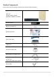
Product Components Please make sure the following components are included as specified below. DVR Unit Desktop: D8DS / D16DS Wall Mount: D8WDS / D16WDS Remote Control Battery 1.
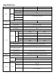
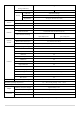
Specifications ITEM Channel, Input Level Input Video Output Audio D16DS/D16WDS D8DS/D8WDS 16CH Composite, 1.0Vp-p, 75ohm 8CH Composite, 1.0Vp-p, 75ohm Signal Format NTSC/PAL Video Loss Check Yes HDMI 1 HDMI (1280x720, 1920x1080) VGA 1 VGA (1024x768, 1280x1024) CVBS 1 BNC SPOT 1 BNC Input & Output 16 CH input & 1 CH output Audio Codec G.711 Sensor Input 4 (NC / NO Selectable) Alarm Out 1 Alarm Out by Sensor, Motion and Video Loss Compression H.
eSATA port 1 (Storage Extension) USB Port RS-485 Network Video & Still Image Network Video & Still Image Huge Backup Yes (up to 24 hours at a time) Menu Display GUI Input Method Front buttons, Remote control, Mouse PTZ control 1 RS-485 Dynamic DNS Yes (Free DDNS) Network Interface 10/100/1000 base-TX Ethernet (RJ-45) Max.
Table of Contents 1. Main Features ............................................................................................................................. 10 2. Initial Boot-up Process.................................................................................................................. 11 2-1. Initial Boot up and Basic Time Setup ........................................................................................ 11 2-2. Setting Daylight Saving Time .................................
5-3-4. Go To First Time .............................................................................................................. 53 5-3-5. Go To Last Time .............................................................................................................. 53 5-3-6. Go To Specific Time ........................................................................................................ 53 5-3-7. Archive List ..................................................................................
7-8-1. Addition, Delete, and Modify of DVR Sites ...................................................................... 79 7-8-2. Connect and Disconnect ................................................................................................. 81 7-8-3. Still-image Capture During Live ....................................................................................... 82 7-8-4. Recording Video on Local PC During Live ...................................................................... 82 7-8-5.
1. Main Features Easy Record, Copy and Setup Easy Search by Thumbnail Preview Easy Copy Easy Network Recording Rate: D16DS: 480fps @ 960H, D8DS: 240fps @ 960H Digital Deterrent, audio message output upon event H.
2. Initial Boot-up Process 2-1. Initial Boot up and Basic Time Setup 1. During the first boot up, the following logo will be displayed. 2. After the logo, select the language and set date and time as specified below. 2-2. Setting Daylight Saving Time To enable Daylight Saving feature/NTP synchronization, take the following steps. 1. Enter the SETUP mode. The default Username is “ADMIN” and Password is “1111”.
2. Go to SETUP > SYSTEM > DATE & TIME SETUP 3. Select ON from the DAYLIGHT SAVING dropdown menu. 2-3. Setting NTP (Network Time Protocol) 1.
2. Select the proper TIME ZONE time. Table2.3.1.
MI Michigan (W) GMT-6 GMT-5 MN Minnesota GMT-6 GMT-5 MS Mississippi GMT-6 GMT-5 MO Missouri GMT-6 GMT-5 MT Montana GMT-7 GMT-6 NE Nebraska GMT-6 GMT-5 NE Nebraska (W) GMT-7 GMT-6 NV Nevada GMT-8 GMT-7 NH New Hampshire GMT-5 GMT-4 NJ New Jersey GMT-5 GMT-4 NM New Mexico GMT-7 GMT-6 NY New York GMT-5 GMT-4 NC North Carolina GMT-5 GMT-4 ND North Dakota GMT-6 GMT-5 ND North Dakota (W) GMT-7 GMT-6 OH Ohio GMT-5 GMT-4 OK Oklahoma GMT-6 GMT-5 OR
3. Front and Rear Panels 3-1. Front Panel DS Desktop Front DS Wall Mount Front Figure 3.1.1. DVR Front panels Table 3.1.1. Front LED and Ports of Desktop Models (D16DS/D8DS) Name POWER HDD USB Port Description LED light is on when power is applied to the system. LED light is on when the system is recording video data. This USB port for archiving footage into a USB device. (USB 2.0 connector) Table 3.1.2.
LIVE mode – Moves Up SEARCH mode – Skips 1min ahead on playback and 1 frame ahead on pause LIVE mode – Moves Right SEARCH mode - Control the play speed (Fast Forward) LIVE mode – Moves Down SEARCH mode - Skips 1min back on playback and 1 frame back on pause LIVE mode – Moves Left SEARCH mode- Select the play speed (Rewind) LIVE mode – Select (Center) SEARCH mode - Play & Pause 3-2. Rear Panel Connectors Do not power this system on before all the connections are attached.
⑪ ETHERNET: Network terminal ⑫ SENSOR IN, ALARM OUT, RS-485: External sensor terminal, External alarm out terminal & RS-485 for PTZ Camera control ⑬ POWER: DC12V input 3-3. Remote Control ① ID: To set the remote control ID. ② REC: To start and stop manual recording ③ SEARCH: To go to SEARCH menu. ④ F/ADV: During playback – To move the playback position 60 seconds forward .
4. Setting up the DVR The following sections detail the initial setup of the DVR. Menu screen will close if user response is not received in 5 minutes. 4-1. Setup – Main Live Screen To enter the setup menu, right click on the mouse and select setup from the submenu or press the setup button on the remote control. Table 4.1.1. Live Screen and Quick Operation Window When the DVR prompts the LOG-IN window, enter the PASSWORD using the virtual keyboard, or the front panel, or the remote control.
4-2. Setup – SYSTEM In the SETUP menu, select the SYSTEM tab. Then, the SYSTEM menu is displayed as pictured below. Navigate through the menu items using the mouse or the remote control and change the value of the menu. Figure 4.2.1. SYSTEM Setup Screen Table 4.2.1. Menu Items in SYSTEM Setup Screen Item Description DESCRIPTION Press the button to view the system information.
Select DAYLIGHT SAVING using the mouse or the remote control and select the appropriate daylight saving time zone. The available options are: OFF: Daylight saving is turned off. USA: Applies the USA daylight saving time. EU: Applies the EU daylight saving time. - Select the GMT AREA using the mouse or the remote control. - Set the time difference with the standard time using the mouse or the button. OTHERS: If the time zone is neither USA nor EU, set the date and time of the daylight saving period.
DVR sends E-MAIL Notification when the NTP server time is faster than the system time with bellow message. “NTP server time is faster than the system time. In this case, NTP server time is ignored to protect the user data. User must set the time manually. SYSTEM TIME: Mon Oct 10 13:46:49 2011 SERVER TIME: Mon Oct 10 13:33:12 2011 DVR ID: DVR IP ADDRESS: 172.16.2.46” SEND EMAIL TRANSMISSION MODE: Select the mail transmission mode (TEXT or VIDEO).
SERVER TYPE: Select GMAIL, HOTMAIL, AOL, YAHOO or MANUAL MAIL SERVER: Enter the appropriate mail server information. MAIL PORT: Assign Mail Port number. SECURE OPTION: Select the secure mail server connection method. (SSL or TLS) ID: Enter the appropriate mail server ID. PASSWORD: Enter the appropriate mail server PASSWORD MAIL TO: Enter the desired email address to receive e-mail reports. MAIL FROM: To set the email address sent to the destination host. UNIT NAME Name the DVR (e.g.
4.2.1.1 Help user to setup DATE & TIME, RECORDING. 1 2 3 4 5 Figure 4.2.3. EZ Record Setup Procedure 4.2.1.
3 4 Figure 4.2.4. EZ NETWORK Setup Procedure ① Select YES in case of setting the network using an internet connection. ② Select Auto Configuration or Manual Configuration and then click TEST button. Figure 4.2.5. EZ NETWORK Setup – Manual Configuration Screen ③ Setup DDNS setting. (Refer to “4.6.2 DDNS”) ④ Finish 4.2.1.
3 4 Figure 4.2.6. EZ NETWORK Setup – Manual Configuration Screen ① Select NO in case internet connection is not being utilized. ② Select Auto Configuration or Manual Configuration and then click TEST button. ③ Select OFF for ENABLE DDNS and click NEXT button.
4-3. Setup – RECORD Mode In the SETUP menu, select the RECORD tab. Then, the RECORD menu is displayed as pictured below. Navigate through the menu items or change the settings using the mouse or the remote control. Figure 4.3.1. RECORD Setup Screen Table 4.3.1. Menu Items in RECORD Setup Screen Menu Item SITE Description Select a channel for applying the following settings using the mouse or the remote control.
Level 1 (Low), Level 2, Level 3, Level 4, and Level 5 (High) RECORDING Assign the recording mode for the selected channel. Options are: Continuous, MODE Motion, Schedule or Disable. SENSOR Select the sensor settings for the selected channel. RECORDING PRE RECORD Enable/disable pre-event recording. Pre-event recording is limited to 20 minutes. POST EVENT Set the post event recording time duration for the specified channel.
4-3-1. Recording Schedules To setup a recording schedule, select SCHEDULE in the RECORD menu. Navigate through the menu items or change the settings using the mouse or the remote control. Select CHANNEL > select NONE, CONTINUOUS or MOTION > HIGHLIGHT AREA To copy a schedule to a different channel, select the channel from the COPY SCHEDULE menu. . Figure 4.3.2.
4-4. Setup – DEVICE Mode In the SETUP menu, select the DEVICE tab. Then, the device menu is displayed as pictured below. Navigate through the menu items or change the settings using the mouse or the remote control. Figure 4.4. DEVICE Setup Screen Table 4.4. Menu Items in DEVICE Setup Screen Item ALARM OUT Description Set the sensor, motion, and video loss for triggering alarm relay HDD Error and Video Loss can trigger beeping. DIGITAL DETERRENT Setup schedule and audio recordings for Digital Deterrent.
Select the type of each sensor. SENSOR Option is Off, Normal Open or Normal Close. 4-4-1. Alarm-Out Figure 4.4.1. ALARM-OUT Setup Screen Table 4.4.1. Item for ALARM-OUT Setup Screen Item Description ALARM OUT Only one Alarm-out is available. SENSOR IN Sensor input from 1 to 4. MOTION ON Camera motion detection from 1 to 4. VIDEO LOSS ON Camera video loss detection from 1 to 4. HDD ERROR HDD Failure or Error ALARM DURATION Set alarm dwell time from 5 to 60 seconds.
Item Description IMPORT FROM USB Import up to 8 sound files from USB. EXPORT TO USB Export the sound file to USB RECORD Select a channel and set up the date and the duration. Select START to export audio to Digital Deterrent. Select the play button to hear message after export. SCHEDULE Schedule the sound file considering the expected situation.
4-4-3. Keyboard Controller & PTZ Setup To control the PTZ functions of the camera, connect the PTZ controller to the RS-485 port on the back of the chassis with CAT5 (or equivalent) cable. ① Connect the RS-485 cables of PTZ camera to the RS-485 port on the rear panel. Figure 4.4.3.1. Device Mode Setup Screen Figure 4.4.3.2. Device Mode Setup Screen ② Open the PTZ sub menu by selecting the submenu button. Figure 4.4.3.3.
Use the PTZ setup screen to select the following options for the camera PTZ controller: - CHANNEL: Channel connected to a PTZ device - CAMERA: Protocol Type - SPEED: 19200, 14400, 9600, 4800, 2400 (Baud rate) - ID: 0-63 Controller (Keyboard Controller): If a PTZ controller is used, select a controller protocol from Controller menu. Set SPEED (Baud Rate) and ID number. Figure 4.4.3.4. Controller Selection Screen 4-4-4. Spot Out Figure 4.4.4. SPOT-OUT Setup Screen Table 4.4.4.
SEQUENCE Set the dwell time for the spot channel display. (1-10sec) DWELL TIME SPOT CHANNEL Select a channel for spot monitoring using the mouse or the remote control and press OK button. 4-4-5. Motion Zone Setup Select MOTION ZONE using the mouse or the remote control and select either PARTIAL ZONE or FULL ZONE using the mouse control. The default value is FULL ZONE. If FULL ZONE is selected, the motion zone grid screen is not displayed. Only set the level of sensitivity for MOTION SENSITIVITY.
4-5. Setup – DISPLAY Mode In the SETUP menu, select the DISPLAY tab. Then, the DISPLAY menu is displayed as pictured below. Navigate through the menu items or change the settings using the mouse or the remote control. To return to the previous setup menu screen, press the ESC button. Figure 4.5. DISPLAY Setup Screen Table 4.5. Menu Items in DISPLAY Setup Screen Item OSD Description Enable/disable on-screen-display.
4-6. Setup – NETWORK Mode Select the NETWORK tab. Then, the network menu is displayed as pictured below. Navigate through the menu items or change the settings using the mouse or the remote control. Figure 4.6. NETWORK Setup Screen Table 4.6. Menu Items in NETWORK Setup Screen Item NETWORK TYPE Description DHCP: DVR will automatically retrieve an IP address. STATIC: Network information must be manually configured.
WEB PORT Enter the port number for connection using web. NETWORK Sets the camera display settings for network streaming. STREAM WIRELESS LAN 1. Connect USB Wifi Dongle to USB connector on DVR. 2. Load the application on your smart phone or PC and enter the WIFI IP ADDRESS. 3. Find the WIFI SSID and enter the password. (shown in image below) 4. Then, the remote viewing and configuration can be used. * There is a distance limitation for the Wireless LAN. 4-6-1. Network Types 4-6-1-1.
Figure 4.6.3. NETWORK Setup Screen – DDNS Table 4.6.2. DDNS Item Description HOST NAME This item allows the user to setup a domain name manually, using virtual keyboard displays as shown. SUBMIT/UPDATE When manual host name input is done, move the cursor to this item and select ON to submit the settings. ezDDNS Enable/disable ezDDNS to register the host name automatically. 4-6-3.
Figure 4.6.4. NETWORK Setup Screen – Network Stream USE MOBILE: When this function is enabled, the frame rate is limited to 15fps@CIF and the video quality is limited to LEVEL 2 for better remote viewing on the mobile phone. 4-7. Setup – USER MANAGEMENT Mode In the SETUP menu, select the USER MANAGEMENT tab. Then, the USER MANAGEMENT menu is displayed as pictured below. Navigate through the menu items or change the settings using the mouse or the remote control. Figure 4.7.
Table 4.7. Menu Items in USER MANAGEMENT Setup Screen Item Description AUTHORITY Only the Admin will have access to the menu. SETUP PASSWORD CHECK: Select the Checkbox to enable the functions or leave the Checkbox blank to disable the functions.
4-8. Setup – STORAGE Mode In the SETUP menu, select the STORAGE tab. Then, the STORAGE menu is displayed as pictured below. Navigate through the menu items or change the settings using the mouse or the remote control. Figure 4.8. STORAGE Setup Screen Table 4.8. Menu Items in STORAGE Setup Screen Item OVERWRITE Description When enabled, the DVR will continue recording and overwrite the oldest existing recorded data once the hard drive is full. When disabled, recording will stop once the hard drive is full.
RECORDING Enable/disable recording limit. LIMIT RECORDING Set the recording limit days. (1- 90 days) LIMIT DAYS If the RECORDING LIMIT DAYS are set to 1, the data will be overwritten after 24 hours. S.M.A.R.T Set the alarm and beep by setting the HDD temperature limit. Alarm will trigger alarm output. Buzzer will trigger beeping from the internal speaker. 4-9. Setup - CONFIG Mode In the SETUP menu, select the CONFIG tab. Then, the configuration menu is displayed as pictured below.
Table 4.9.1. CONFIGURATION Setup Item Description EXPORT TO User can save the current configuration (Setting values) of the DVR to the USB USB flash drive. Plug in the USB flash on the front panel and press the button to start the saving process. IMPORT User can upload the configuration of the DVR to another DVR using the USB FROM USB Flash drive. Plug in the USB flash drive on the front panel and press the button to start the loading process.
Figure 4.9.2 Figure 4.9.3 Figure 4.9.4 NOTICE 1. If selecting REBOOT LATER, the upgraded software will not be applied until the system reboots. 2. If selecting REBOOT NOW when the USB flash drive is plugged, the following message will pop up. Remove the USB flash drive and select OK. 5. Live, Search and Playback 5-1. Live View In the Live screen, video inputs from the cameras are displayed as they are configured in the Display Setup screen.
Figure 5.1.1. Live Screen and Quick Operation Window Table 5.1.1. Status Indicator Icons in Live Viewing Screen Icon Description Indicates the DVR is locked. Note) to unlock, right click on the live view screen and click on Unlock. Audio mute. To select audio output, press the Audio after click the right button on the mouse. Toggle from Audio 1 to 4, mute in order. Indicates that alarm is set. To set the alarm function, press the Alarm button on the front panel. Indicates that alarm output is activated.
Displays the amount of recording on the hard disk from 0-99%. Indicates that HDD is recycled. Continuous recording in progress. Manual recording in progress. To set the Manual recording mode, press the Record button on the front panel. Motion alarm recording in progress. Sensor recording in progress. Right click the mouse, and the quick operation window will be displayed as below. Figure 5.1.2. Quick Operation Window Table 5.1.2.
D16DS: (Channel 1 through 16, Audio Mute). D8DS: (Channel 1 through 8, Audio Mute). SEARCH Select this option to enter the Search menu. SNAPSHOT Click this option to create a snapshot of selected channel image. (JPEG STILL IMAGE) CAMERA PTZ Select this option and the PTZ user interface will appear. ENABLE MAIN Select this option to enable/disable sequence function. MONITOR SEQUENCE ENABLE MANUAL Manual Record button. Click this button to enable manual recording.
SYSTEM Lock/Unlock Setup button. LOCK SYSTEM Click this button to shutdown system.
5-1-1. PTZ Control Table 5.1.3. Menu Items in PTZ Control Window Item Description INITIALIZE Initialize the PTZ settings of the selected camera PAN/TILT Select PAN/TILT using the ▲▼◀ and ▶button, then press SEL. Adjust the tilt (UP/DOWN)/pan (LEFT/RIGHT) position using the ▲▼◀and ▶ buttons. ZOOM/FOCUS Select ZOM/FOCUS using the▲▼◀ and ▶ buttons, then press SEL. Adjust the zoom (UP/DOWN)/ focus (LEFT/ RIGHT)position using the ▲▼◀ and ▶ buttons. OSD Select OSD to enter the menu.
2. Click the left button of the mouse and drag to make rectangular shape. 5-3. SEARCH Screen To enter the search screen menu, select SEARCH menu on the screen using the mouse or press SEARCH icon on live screen. Figure 5.3. Search Screen There are 7 ways of search menu such as EZSEARCH, TIME LINE (Calendar), EVENT, GO TO FIRST TIME, GO TO LAST TIME, GO TO SPECIFIC TIME, ARCHIVE LIST, and LOG LIST on the screen.
5-3-1. EZSearch The EZSearch window is used to find stored video with ease using the thumb nail playback screen. Figure 5.3.1.1. Calendar Screen Figure 5.3.1.2. Channel Selection Screen Figure 5.3.1.3. 24 Hourly Thumbnail Screen Figure 5.3.1.4. Minute Thumbnail Screen Figure 5.3.1.5. Play Mode Screen 1. When the EZSearch menu is selected, the user can see a calendar, which displays recorded dates with highlights. Select a specific date on a calendar. 2. Select a channel from Channel Selection Screen.
5-3-2. Time Line Search The CALENDAR Search window is used to find the stored video by using the time line bar. Figure 5.3.2.1. Calendar Screen Figure 5.3.2.2. Time-Line Search Screen When the Timeline menu is selected, the user can see a calendar, which displays recorded dates with highlights. Select a specific date and time. Click and drag the red time indicator bar to the desired hour. User can select a specific minutes using a button in the above red box.
Figure 5.3.3.2. Event Search Screen 5-3-4. Go To First Time You can access from the oldest recorded data on the DVR hard drive by selecting GO TO FIRST TIME on the SEARCH window. Press the PREV to return to the SEARCH window. 5-3-5. Go To Last Time You can access from the last minute recorded data on the DVR hard drive by selecting GO TO LAST TME on the SEARCH window. Press the PREV to return to the SEARCH window. 5-3-6.
5-3-8. Log List You can access the LOG list search screen by selecting LOG on the SEARCH window. Figure 5.3.8. Log List Screen When the Log menu is selected, the user can see a calendar, which has a log data. Select a specific date and press NEXT button, and then the log data will be displayed. Press the SAVE button to save the data and then the data is saved as a text file format. 5-4. Play Mode During playback of a recorded event, the mode changes from SEARCH to PLAY.
Jump/Step backward. The playback position moves 60 seconds backward. Press to play or pause recorded video. Jump/Step forward. Playback position moves 60 seconds forward. 2x, 4x, 8x,16x, 32x speeds at 4 split screen 2x, 4x, 8x,16x at 9 split screen 2x, 4x, 8x at 16 split screen Single Channel forward playback speed 1x, 2x, 4x, 8x, 16x, 32x, 64x Slow Mode play. Forward playback speed x1/4, x1/2 Press to backup the video. EZCopy button.
6-2. Video Backup onto USB Flash Drive during playback Video can be captured and archived onto the USB flash drive or a hard drive while playing back the recorded video. In playback mode, press the 1. When you press BACKUP button to launch the backup function. BACKUP button on the selected channel or all channels, the DVR will ask whether to archive a Still Image, a NSF or AVI and select the proper media type. 2. Select USB STICK (Flash Drive) to back up less than an hour.
6-3. EZCopy: Video Backup onto USB Flash Drive during playback Using EZCopy feature, Video can be easily archived onto the USB flash drive or a hard drive. In playback mode, press the EZCOPY button to launch the backup function. 1. Press EZCOPY button on the selected channel or all channels. 2. Then, EZCOPY START time will display. 3. Move time bar cursor to the time of end of backup and press EZCOPY button. Then, EZCOPY STOP time will display. 4. EZCOPY window will display.
5. After backup format is selected, also select media type and channel(s) to archive the data to the media. 6-4. Transferring Still Images or Video from the ARCHIVE List The stored data in the hard drive can be found in the ARCHIVE list in the SEARCH window. User can back up still images or video into the storage device from the ARCHIVE list. 1. Select the date to begin searching and navigate through the days using the mouse or the remote control. 2.
Figure 6.3.1. Archive Search Screen 6-5. Playback of Backup Video 6-5-1. AVI Format AVI format: AVI format video can be played back by Window Media Player™ or other media player that is compatible with AVI format video. 1. Please install the UMSDecoderFilter that the DVR copies “DvrPlayer” folder on USB flash drive with the video. UMSDecoderFilter is exported to the “/DvrPlayer” folder of the USB drive. 2.
6-5-2. NSF Format NSF format: NSF format video can be played back using the HDplayer that the DVR copies to “DvrPlayer” folder on USB flash drive with video. Use the mouse scroll to use digital zoom in and out feature.
7. Network Access Using the Multi-Sites Network Viewer 7-1. Overview The SpecoTech Multi Client is a multiple site monitoring client software with; video, audio, and alarm signals from the DVRs over networks. The SpecoTech Multi Client does not limit the number of DVR units to register. The program displays up to 16 DVRs and supports dual monitors. On the program, user may control PTZ cameras on the DVRs.
7-3. Installation of the Program 1. Insert the provided CD in the CD drive and double-click “SpecoTech Multi Client (XXXX).exe” 2. Select a destination folder and click “Next”. 3. Select the program folder and click “Next”. 4. The installation status screen is displayed. 5. After the installation is completed, “SpecoTech Multi Client” icon displays on the desktop screen.
7-4. Live Window When installation is completed, double click the “SpecoTech Multi Client” icon on your desktop to start the program. 7-4-1. Main User Interface 7-4-2. Control Buttons Button Description Click this icon to run a playback window to search and play videos that LOCAL PLAYBACK are recorded in the local PC. Click this icon to run a playback window to search and play videos that REMOTE PLAYBACK are recorded in the remote DVR.
Click this icon to setup configuration of UMS MULTI CLIENT. SETUP Click this icon to capture a still image. CAPTURE Opens list of events logged by the UMS Multi Client. EVENT LIST Click this icon to play/pause live video. PAUSE Click this icon to turn on/off alarm outputs. ALARM ON Enable or disable recording of live video to local disk, which has set in RECORD ON setup menu. Use the volume control bar to set the audio level.
7-5-2. Main Control Panel Button Description Click this icon to run a playback window to search and play videos that LOCAL PLAYBACK are recorded in the local PC. Click this icon to run a playback window to search and play videos that REMOTE PLAYBACK are recorded in the remote DVR. THUMBNAIL REFRESH: Click this icon to refresh and renew thumbnail image of the connected sites. SITE ADDITION: Click this icon to open „Site Addition‟ window.
To select the channel to playback. The calendar shows dates with recorded video in color. To display the recorded data of selected channel or all channels on a time line scale. To change a timeline scale from 24 hours to 60 minutes. The timeline shows recorded data in color on the bar. You can adjust the timeline scale and move it to the time you wish to playback. Then click the play icon to display the recorded video. Playback buttons. Thumbnail search over the network.
7-6-2. Event Event log can be archived and searched. Event Log: Specify the location to save event logs and select event to archive.
Event Search: Event log can be searched from the selected time. 7-6-3. Record Record Setup: You can set the recording conditions as the following; Always, Event, or Auto record. And you can also select target DVR/DVRs and channel/channels. When you set the recording condition to event, you can set event for motion or alarm with duration.
Record Local Storage Setup: You can select the local disk to record and the amount of disk space you want to allow the program to use for recording. You can also select the option to overwrite data or stop recording when the maximum amount of disk space is full. 7-6-4. Display You can select the OSD (On Screen Display) to be displayed.
7-6-5. Language English, French and Spanish is selectable. 7-6-6. About “About” provides network client version information.
7-7. Remote Setup The menu settings for the DVR unit can be set over network. Put the cursor of the mouse on the channel, which is connected to the site and right click on the mouse to open the submenu. Then the following window is displayed as below. Select the REMOTE SETUP. Then the setup window is displayed. The specified menu screen is displayed on the upper left of the screen. Enter the password of the DVR when prompted.
7-7-1. System Select System to set system and time settings. DATE DISPLAY FORMAT: Select the date display format. CLIENT ACCCESS: Enable/Disable remote access through network client software. NTP SETUP: Sets whether to synchronize the time using NTP server or not. o Primary SNTP Server: Input the NTP primary server address. o Secondary SNTP Server: Input the NTP secondary server address. o Time Zone: Select the time zone.
7-7-2. Record Select RECORD tab to set the recording conditions. These settings apply to the specified channel only. Recording Setup o RESOLUTION: Sets the resolution for the recordings. The set value applies to an individual channel. o FRAME RATE: Sets the recording rate. o QUALITY: Sets the image quality in 5 levels. o RECORDING: Sets the recording mode. o RECORDING MODE: CONTINUOS, SCHEDULE, MOTION o PRE RECORD: Sets whether to perform or not pre recording.
7-7-3. Device Select Device to set Spot Out, Enable/Disable CVBS Out, motion zone. ALARM OUT: Set the sensor, motion, and video loss for triggering alarm relay HDD Error and Video Loss can trigger beeping. DIGITAL DETERRENT: Set the schedule of digital deterrent function and upload the sound file to DVR. CONTROLLER: Set the controller baud rate and ID. PTZ: Set the PTZ baud rate, protocol, and ID. MOTION: Setup the motion detection area and the sensitivity.
7-7-4. Display Select the DISPLAY tab to set the DISPLAY conditions. These settings apply to all channels. OSD: Sets whether to display or not date and time as well as channel number on the screen. OSD CONTRAST: Adjust the character contrast on the screen. MAIN MONITOR SEQUENCE: Setting for automatically switching the displayed video. SEQUENCE DWELL TIME: Sets the interval for automatically switching the screens.
7-7-5. Network NETWORK TYPE ( Cannot be altered remotely ) o STATIC: The address setting mode is manual. Input IP, Gateway, Subnet Mask, and DNS IP. o DHCP: The address setting mode is automatic.
7-7-6. User Management Select the USER MANAGEMENT tab to set the DISPLAY conditions. 7-7-7. Storage Select Storage to configure continued recording settings by overwriting the hard disk and the storage period for the recording data. OVERWRITE: RECORD LIMIT: Sets whether to limit or not the recording data storage period. S.M.A.R.T.: Sets the TEMPERATURE LIMIT of the Hard Disk to trigger the ALARM and the Select on to continue recording by overwriting when the hard disk becomes full. BUZZER.
7-7-8. Remote Upgrade Shows the current Firmware version installed on DVR. Browse: Select BROWSE to locate the firmware file. Upgrade: Select UPGRADE to upgrade the firmware of the DVR.
7-8. Operation 7-8-1. Addition, Delete, and Modify of DVR Sites 7-8-1-1. Addition of Sites 1. Click SITE ADDITION button. And then the following window will be displayed as below. o Site Name: Input a name that properly describes a site. o IP Address: Input IP address (Public IP address of a router that DVR is connected.) or Domain name o Port Number: Default Port Number is “5445”. o ID: Input ID of DVR. Default ID is “admin”. o Password: Input network password of DVR. Default Password is “1111”.
7-8-1-3. Modify of Sites 1. Select the site/sites to modify from the directory window. 2. Click NET FINDER button. And then the following window will be displayed as below. 3. Click MODIFY button. And then the modified information is displayed as below.
7-8-2. Connect and Disconnect 7-8-2-1. Connect 1. Select site/sites to connect from the directory window. 2. Click CONNECT button, and then site/sites displays/display as connected. 7-8-2-2. Disconnect 1. Select site/sites to disconnect from the directory window. 2. Click DISCONNECT button, and then selected site/sites disconnected.
7-8-3. Still-image Capture During Live 1. Double-click a channel to capture from the display screen. (Otherwise all channels will be captured.). 2. Click CAPTURE button. And then a Capture window will be displayed as below. 3. Set Save Path, File Name, and File Format. And then click OK button. 4. Still image is saved as set in Capture window. 7-8-4. Recording Video on Local PC During Live 1. Click SETUP button. And then a setup window will be displayed as below. 2. Select Record and set the values.
4. Click RECORD ON button. And the color of button is changed. 5. Live video data is recorded as set in Record and Disk setup. These video data can be searched and play-backed with Local Playback. 7-8-5. Local Playback and Remote Playback 7-8-5-1. Playback of Recorded Video on a Local PC 1. Click LOCAL PLAYBACK. And then Playback Window will be displayed over the Live Window.
2. Select site/sites to connect from the directory window. 3. Click CONNECT button. And then Green bar displays on Search calendar and timeline scale window. 6. Move the marker on the timeline scale to where there is video data and press the PLAY button. 7. Video data that is recorded on local PC will be play-backed. 8. Use the mouse scroll to digitally zoom in and out from a single channel display. 7-8-5-2. Playback of Recorded Video on Remote DVR 1. Click REMOTE PLAYBACK.
3. Click CONNECT. And then Green bar displays on Search calendar and timeline scale window. 4. Move the marker on the timeline scale to where there is video data and press the PLAY button. 5. Video data that is recorded on the remote DVR is play-backed. 7-8-6. AVI Backup during Playback You can back up the recorded videos in AVI format during playback. 1. Double-click the target channel to backup. 2. Select the beginning time by using the search calendar and timeline scale bar. 3.
the selected starting point and the ending point on the timeline scale bar will be marked in green. 5. Click BACKUP. And then the BACKUP window will be displayed as below. 6. You can also set the beginning time and ending time on this window. After selecting a channel for backup, click the OK button. The backup will begin.
7. AVI video data is recorded as set in AVI Backup window. AVI format video can be played back by using Window Media Player™ or other media player that is compatible with AVI format video. 8. Network Access Using the Web-Browser Viewer The DVR provides a live remote monitoring feature by web-browser viewer. (NOTE: Web-Brower is only available for Internet Explorer) 1. Check the IP address of the DVR from SETUP>SYSTEM>DESCRIPTION>IP ADDRESS or 2.
5. The Web Browser Viewer will be displayed as below after the ActiveX installation 6. Click the CONNECT button on the Left upper corner of web-viewer. Then “Connect” dialog is displayed.
Site Name: Input a name that properly describes a site. IP Address: Input IP address (Public IP address of a router that DVR is connected.) or Domain name Port Number: Default Port Number is “5445”. ID: Input ID of DVR. Default ID is “admin”. Password: Input network password of DVR. Default Password is “1111”. 7. Then the cameras connected to the DVR are displayed on the screen. 8. Use mouse scroll to digitally zoom in and out from a single channel display. 9.
Notice SPECO Player is for the DS, RS, WRS and HD series DVRs. SPECO VIEWER is not compatible with the T Series DVR‟s (TH, TN or TL) or the PC Series DVR‟s. 9-1-1. Live 1. Open the installed “Speco Player” App and click button to add a remote device. 2. Enter the site name, IP or DDNS address, Network Port number (default 5445), ID(default admin) and Password (default 1111). Then, click “Save” button. * Note: Network Port and Web Port must be forwarded before adding a new site. 3.
5. To select the display mode(1, 4, 9, 10 or 16 split display), tap the arrow menus button 6. Drag and drop channels Touch and drag one channel to the other channel to swap the channel location. To swap the channel, drag a channel to another channel. 7. Digital Zoom In-Out Double tap on the desired channel to view in 1channel mode. Then use the iPhone zoom feature using two fingers to pinch the screen to zoom in or out on the video image.
2. The app will display the selected channel(s). Double tap the channel screen to switch 1 channel display to 4, 8, 10, 16 channels split display depending on the DVR. 3. Tap the menu button. Then Playback menu icons will display. 9-2. App Viewer for Android Phone 1. Enter the Android Market. 2. Search “Speco Player” in the Android Market and install the “Speco Player” app. Notice SPECO Player is for the DS, RS, WRS and HD series DVRs.
9-2-1. Live 1. Open the installed “Speco Player” App and select the Live Preview. Then click the menu button of the phone to add a remote device. 2. Select the registered device and select LIVE VIEW and select up to 4 channels to monitor. Then click START button. 3. The app will display the selected channel(s). Double tap the channel screen to switch 1 channel display to 4 channels split display. 9-2-2. Playback 1. Select the registered device and select PLAYBACK and select up to 4 channels to search.
9-2-3.PTZ Control To control the PTZ function of the camera, tap the channel screen, then the channel name will be highlighted in Yellow. Using the PTZ menu icons on the screen, control PTZF.
APPENDIX: Network Connection - LAN 1. Install the network client software from the supplied CD. 2. Check the IP address from SETUP > SYSTEM > DESCRIPTION or SETUP>NETWORK of DVR. 3. Run the network client software.
4. Input Site Name, Site Address (IP address), Port Number, and Password on the connect window. Site Name: Input a name that properly describes a site. IP Address: Input IP address Port Number: Default Port Number is “5445”. ID: Input ID of DVR. Default ID is “admin”. Password: Input network password of DVR. Default Password is “1111”. 5. Select a site by checking the box, and Press 96 button to connect to the site.
APPENDIX: Network Connection – Internet and DDNS Dynamic Domain Name System (DDNS) allows a domain name to be constantly synchronized with a dynamic IP address. A current dynamic IP address is being associated with a static domain name. 1. Go to SETUP>NETWORK>DDNS and set the DDNS SERVER to ON. If you set ezDDNS to ON, the host name is automatically generated and registered. 2. Go to SETUP>NETWORK>DDNS>HOST NAME. Manually enter a domain name using the virtual keyboard and click ENTER button.
3. When a manual host name is completed, Go to SETUP>NETWORK>DDNS>SUBMIT/UPDATE and select ON to submit the settings on the SPECO DDNS. Once the setting is completed, the DDNS address will be: http://hostname.ddns.specoddns.net For example, if you enter the host name as “D16DS”, then the address will be: http://d16ds.ddns.specoddns.net 4. When DDNS setting is done, click the APPLY button. Otherwise DDNS setting will not be applied. 5. When you exit SETUP menu, DDNS NOTIFIY window will pop up. 6.
8. Port forward the NETWORK PORT (Default: 5445) and WEB PORT (Default: 80) of the private IP Address of the DVR on the network router. Please refer to the user manual and guide for the detailed steps for port forwarding for specific router model. 6. Run the network client software. 7. Input Site Name, Site Address (IP address), Port No., and Password on the connect window. 8. Site Name: Input a name that properly describes a site.
APPENDIX: E-SATA CONNECTION Please read the following instructions before using the E-SATA port. Failure to do so may cause serious damage to the recorded video. SPECO is not responsible for data loss caused by improper usage. Use ONLY a new HDD or a HDD that is approved for the unit. Turn off the DVR before plugging the E-SATA HDD. DO NOT disconnect the E-SATA port while the DVR power is on. The purpose of the E-SATA port is to extend recording capacity.