
User manual


RS232C Interface Page 6
Columbia Weather Systems, Inc.
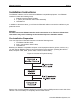
Inside are two DIP switches marked S1 and S2. The slide switches on each DIP switch are
numbered 1 through 8.
Switches marked S1 select the data transmission speed, character length, parity and the output
repetition length. Switches marked S2 determine how the control and communication lines are
to be used.
In addition, there are two pins marked RTS. This is the REQUEST TO SEND signal. Typically,
you should leave the pins unconnected by leaving the blue jumper positioned on only one pin.
(Refer to Section 4: Technical Information for more information on this feature.)
There are two connectors on the rear of the RS232C Interface. The connector on the left (J1)
connects the 20 –conductor ribbon cable to the weather station. The connector on the right (J2)
connects the Interface to the user’s compatible equipment. Do not connect anything at this
time.
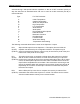
Setting Switch 1
To set this switch you will need the following information from the device you are connecting to
the weather station via the Interface:
♦ Baud Rate
♦ Number of data bits
♦ Number of stop bits
♦ If you equipment checks parity
♦ If parity is Odd or Even
Data can be sent automatically or at any of four different repetition rates. Positions 7 and 8 of
S1 control the automatic repetition rate.
Eight slide switches on DIP switch S1 control the following:
Baud Rate
Data Bits Stop Bits Parity Enable Parity Odd/Even Repetition Rate
1 2 3 4 5 6 7 8
0 0= 300 0=7 0=1 0=No 0=Odd 0 0=Contin.
1 0= 600 1 =8 1=2 1=Yes 1=Even 1 0=15 Min.
0 1= 1200 0 1=30 Min.
1 1=9600 1 1=60 Min.
(0 = OFF 1 = ON)
A typical setting for 1200 baud, 8 data bits, 1 stop bit, even parity and an automatic data output,
repetition rate of 30 minutes would be as follows (see Figure 4):
S1 1 2 3 4 5 6 7 8
Off On On Off On On Off On