COLUMBIA L • WL • CWH SERIES BOILERS INSTALLATION, OPERATION and MAINTENANCE MANUAL COLUMBIA BOILER COMPANY P.O. BOX 1070, POTTSTOWN, PA 19464 PHONE: 610-323-2700 • FAX: 610-323-7292 www.columbiaboiler.
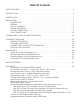
Table Of Contents PARTS WARRANTY . . . . . . . . . . . . . . . . . . . . . . . . . . . . . . . . . . . . . . . . . . . . . . . . . . . . . . . . . . . . .2 INTRODUCTION . . . . . . . . . . . . . . . . . . . . . . . . . . . . . . . . . . . . . . . . . . . . . . . . . . . . . . . . . . . . . . .3 SERVICE POLICY . . . . . . . . . . . . . . . . . . . . . . . . . . . . . . . . . . . . . . . . . . . . . . . . . . . . . . . . . . . . . .4 INSTALLATION . . . . . . . . . . . . . . . . . . . . . . . . . . . . . . . .
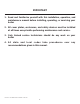
IMPORTANT 1. Read and familiarize yourself with this installation, operation, and maintenance manual before installing, operating, or servicing your boiler. 2. All cover plates, enclosures, and safety devices must be installed at all times except while performing maintenance and service. 3. Only trained service technicians should do any work on your boiler. 4. All state and local codes take precedence over any recommendations given in this manual. LWLCWH COLUMBIA BOILER COMPANY REV.
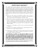
LIMITED PARTS WARRANTY The Columbia Boiler Company (hereinafter Columbia) warrants the burner components and controls installed on its boiler/burner units to be free from defects in material and workmanship under normal use and service for 12 months from the date of installation or 18 months from the date of manufacture, whichever date occurs first and is subject to warranty approval by the manufacturer of the specific components.
INTRODUCTION Series L and WL Water Tube Boilers The Columbia Models L and WL are water tube boilers designed for hot water, and/or low pressure steam applications. These units are manufactured to the specifications set forth by Section IV of the ASME Boiler and Pressure Vessel Code. Boilers are inspected and stamped for conformity to requirements of the National Board of Boiler and Pressure Vessel Inspectors. All boilers are designed to be fired using No.
SERVICE POLICY Anything mechanical will inevitably need servicing. Steam and hot water boilers are routinely serviced by the installer or another boiler maintenance company. Occasionally the service technician may be unable to determine the cause of the problem. In this situation, the dealer or service organization should contact the selling distributor for help. Should the problem persist, the distributor will contact the sales representative for assistance.
INSTALLATION BEFORE BEGINNING INSTALLATION, CAREFULLY STUDY THESE INSTRUCTIONS AND ALL CHARTS, DRAWINGS, AND DIAGRAMS SHIPPED WITH THE BOILER. Installation must follow all state and local code requirements, Fire and Underwriters regulations, and standard plumbing practices. The electrical installation shall be in accordance with the National Electrical Code. Remove all boiler components from packaging and inspect prior to assembly to ensure that damage has not occurred in shipping.
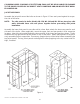
COLUMBIA BOILER COMPANY OF POTTSTOWN SHALL NOT BE HELD LIABLE FOR DAMAGE TO THE BOILER CAUSED BY INCORRECT VENT CONDITIONS AND/OR INSUFFICIENT BURNER MAKEUP AIR. JACKET ASSEMBLY Assemble the jacket kit around the boiler as shown in Figure 1. Place each panel against its respective side of the boiler. NOTE: The side panels for boiler Models WL-120, WL-140 and WL-180 are two piece side walls. Assemble these side wall pieces together before proceeding with jacket installation.
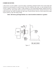
BURNER MOUNTING If the burner is to be installed on site, first apply a gasketing material between the burner flange and the burner mounting plate to seal the burner. Use a non-asbestos fiber rope, or a wet insulating material for a gasket, as shown in Figure 2. Wet insulation is the preferred gasketing material because it compresses into a flat gasket which conforms to and fills any and all voids. Secure the burner in the boiler using the four bolts supplied with the burner.
BOILER CONNECTIONS Drains All Columbia Boiler units have (4) washouts located around the lower corners of the boiler for drainage purposes. Install a pipe nipple and ball valve in a least one washout for use as a drain. If a washout is not needed, plug it by using the proper size nipple and a pipe cap. DO NOT use a pipe plug. Low Water Cut-Offs All Columbia boilers are supplied with a single low water cut-off (LWCO) as standard equipment. Several boiler applications may require a secondary LWCO.
LENGTH OF PROBE ROD IN “WL” AND UP TO” CWH-780 & UP” SERIES BOILERS BOILER MODEL WL-60 CWH-780 WL-90 CWH-1200 WL-120 CWH-1510 WL-140 CWH-1810 WL-180 CWH-2460 ROD LENGTH 14-1/2" 14-1/2" 14-1/2" 14-1/2" 14-1/2" Table 1b Other secondary LWCO s include combination LWCO / Water Feeders. These devices are typically connected externally using an equalizing line, and piped into the available 1" NPT fittings found in boiler top, and left side or front.
Safety Valve / Relief Valve All safety or relief valves are located in the rear center fitting on top of the boiler. A 15 PSI Steam Safety Valve is supplied for steam boiler and water heater applications. A 30 PSI Water Relief Valve is used for hot water applications. All safety and relief valves should be safely piped away from the boiler without reducing the valve s outlet port size. Steam Supply Pipe the steam lines to the largest fitting or flange located on top of the boiler.
FUEL CONNECTIONS OIL SUPPLY PIPING Connect burner to oil supply. Refer to fuel unit manufacturer literature for piping, connections, lift and tank installation. If such information is unavailable use the following guidelines: Fuel supply “level with” or “above” burner: A single stage fuel unit connected to the fuel supply with a single supply line is the most common type of installation for these conditions. Manual venting of the fuel oil is usually required on initial start up.
GAS SUPPLY PIPING Contact your local gas company to ensure that adequate gas service is available, and to review applicable installation codes for your area. The minimum gas supply pressure required by the burner is five inches water column for the GL-18, GL-20, GL-22, GL-24, CWH-170, CWH-240, CWH-300, CWH-390 and seven inches water column for the GL-30, GL-32, CWH-470, CWH-610, CWH-780, CWH-1200 CWH-1510, CWH-1810, CWH-2460 and all WL Series boilers.
REQUIRED INPUT - CUBIC FEET OF GAS PER HOUR GAS TYPE L-18 CWH-170 L-20 CWH-240 L-22 CWH-300 L-24 CWH-390 L-30 CWH-475 L-32 CWH-610 NATURAL 168 252 336 420 560 700 PROPANE 67 101 134 168 224 280 GAS TYPE WL-60 CWH-780 WL-90 CWH-1200 WL-120 CWH-1510 WL-140 CWH-1810 WL-180 CWH-2460 ROD LENGTH 840 1260 1680 1960 2520 PROPANE 336 504 672 784 1008 CAPACITY OF PIPE - CUBIC FEET OF GAS PER HOUR AT 0.2" W.C.
Gas lines should be tested for leaks. Your gas company may wish to witness this test. Do not exceed the maximum pressures allowed by the valve train. Additional gas piping information is included in the burner section of this manual. COMBUSTION AIR It is essential that provisions are made for a fresh supply of outside air into the boiler room to insure complete combustion, proper boiler efficiency, and a clean fire.
REQUIRED BOILER MAKE-UP AIR BOILER SIZE (HORSEPOWER) BTU INPUT OPENING MIN.
CLEANING AND FILLING A NEW STEAM BOILER Note: The following procedure is for steam boilers only. This procedure should also be used for indirect water boilers (CWH-Series). In order to minimize the corrosive effects of raw water oxidation on the boiler, the water must be heated to at least 180°F immediately after entering the boiler, in order to drive off the corrosive dissolved gases. This applies to all water - whether from a well, a spring, or from the local municipal water system.
4. Mix the chemicals with water and pour into the boiler through the safety valve opening. 5. Replace the safety valve. 6. Start the firing equipment. 7. Boil the water for at least five hours. 8. Stop the firing equipment. 9. Drain the boiler to a location where hot water can be discharged safely. 10. Wash the boiler thoroughly using a hose with sufficient pressure. 11. Fill the boiler to the normal waterline. 12. Add boiler water treatment as prescribed by a water treatment specialist. 13.
OPERATING THE BOILER NOTE: Although each factory packaged unit has been test fired at the factory, each boiler must be “set up” for the conditions on location. Improper combustion settings may cause the burner to operate erratically, resulting in boiler shutdowns, lost time, and unnecessary service expenses.
STARTING THE BOILER WARNING: NEVER OPERATE A BOILER WITHOUT BEING SURE IT IS FILLED WITH WATER AND THAT PROPER WATER TREATMENT CHEMICALS HAVE BEEN ADDED. Allow the boiler to fill with water to its normal operating level. Supply power to the boiler disconnects. NOTE: The burner will not operate when the boiler has reached its normal water level, until the reset button on the manually reset, probe type, low water cut-off is pushed. NOTE: Combustion efficiency must be checked at this time.
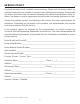
BURNER START UP AND TEST INFORMATION For a new boiler start up, or for troubleshooting an existing installation, the following information is essential for effective service assistance. Boiler Model_________________ Serial No.________________ N.B. No.______________________ Burner Model________________ Invoice No._______________ Serial No.
CONTROL DESCRIPTIONS STEAM BOILERS Pressure Controls All Columbia steam boilers are controlled by both operating and safety limit Pressure Control. Both devices are adjustable and use pressure actuated mercury switches. These switches open when pressure reaches the main scale set point value, cycling the boiler off. The operating Pressure Control also has an adjustable differential feature.
than that of the primary LWCO. This relay must be manually reset if power is interrupted to the control circuit for any reason. During operation, if the water level falls below the probe rod, the energized circuit breaks, causing the relay to open, disconnecting power to the burner. Restore the water level to the normal operating level, then manually reset the control to resume operation.
HOT WATER BOILERS Aquastat® Controllers All Columbia water boilers and indirect water heaters are controlled by both operating (Honeywell L4006A-100-240F) and safety limit (Honeywell L4006E 130-290F) Aquastat® Controllers. The safety limit should always be adjusted higher than the operating limit under normal operating conditions. If for any reason the water temperature would exceed the operating limit and not trip the control, the safety limit should break the circuit to the burner.
MAINTENANCE RECORD KEEPING All manufacturers literature, spare parts lists, operating and maintenance procedures should be maintained in the boiler room at all times. A log book should also be provided to record maintenance work, inspections, and other performance test results. General Clean the boiler and heating surfaces whenever required. The frequency of the cleaning required to maintain the boiler at peak efficiency will be determined only by frequent inspections. It cannot be predicted.
Monthly Boiler Check & Maintenance List 1. 2. 3. 4. 5. 6. Test all fan interlocks. Check main burner safety shut off valve(s) for operational closure. Oil fired; check fuel pressure interlocks when provided. Gas fired; check high and low fuel pressure switches. Flue or stack dampers; make visual inspection for proper operation. Inspect heating surfaces for cleanness. Semiannual Boiler Check & Maintenance List 1. 2. 3. 4. Inspect burner components; Refer to burner manufacturers instructions.
Gauge Glass Replacement Instructions: 1. Make absolutely certain that the new water level gauge glass is 5/8" O.D. and is the correct length Pyrex® red line, high pressure, high temperature glass tubing with fire polished ends. 2. Close gauge glass valves. 3. Remove gauge glass protector. 4. Remove the old glass, gaskets, brass washers, and brass nuts. Be sure threads on the gauge valves are clean. 5. Install brass nuts, brass washers, and gaskets on each end of the gauge glass. 6.
WATER TREATMENT Proper treatment of make-up water and boiler water is necessary to prevent scale, or other deposits, and corrosion within the boiler. The absence of adequate external and internal treatments can lead to operational upsets or total boiler failure. Where a choice is available, pretreatment external to the boiler is always preferred and more reliable than treatment within the boiler. Obtain, and follow, Instructions for feedwater treatment, prepared by a competent feedwater chemist.
Below a pH of 5.0 the water is acidic enough to dissolve the steel boiler plates. Under these conditions the steel gradually becomes thinner and thinner until its destruction. At a pH between 5 and 9.4 pitting of shell plates will occur at a rate depending on the amount of dissolved oxygen in the boiler. Dissolved Oxygen Dissolved oxygen is caused by the solubility of atmospheric oxygen into the supply water. Aeration of the city water supply is frequently used to remove other noxious gasses.
Alkalinity The alkalinity of boiler water should be sufficiently high enough to protect shell and plates against acidic corrosion, but not high enough to produce carryover. A minimum value for alkalinity for adequate protection is 200 PPM. High boiler alkalinity, which is in excess of 700 PPM. should be avoided. Values higher than this can lead to embrittlment of the steel. Phosphates Phosphates are used to react with calcium hardness in the boiler water.
APPENDICES Recirculation Whenever hot water is supplied for process to some distant point, the water in the connecting line will cool, making it necessary to draw off the cool water before hot is obtained. In some applications where lines are long and large, this could be a troublesome factor, but it can be readily corrected by installing a circulator pump.
LWLCWH COLUMBIA BOILER COMPANY REV.
SPECIFICATIONS AND DATA LWLCWH COLUMBIA BOILER COMPANY REV.
LWLCWH COLUMBIA BOILER COMPANY REV.
LWLCWH COLUMBIA BOILER COMPANY REV.
LWLCWH COLUMBIA BOILER COMPANY REV.
SPECIFICATIONS AND DATA 14”(2) LWLCWH COLUMBIA BOILER COMPANY REV.
REPLACEMENT PARTS FOR REF. No.
REPLACEMENT PARTS FOR REF. No.
REPLACEMENT PARTS FOR REF. No.
REPLACEMENT PARTS FOR REF. No. WL-SERIES BOILERS and CWH-780 thru CWH-2460 WATER HEATERS DESCRIPTION BOILER MODEL ITEM NUMBER‡ 4B PRESSURE CONTROL, SAFETY LIMIT, 2-15 PSI ALL 553605 __________________________________________________________________________________________ 4C STEAM SYPON, STRAIGHT ALL 559310 __________________________________________________________________________________________ 4D STEAM GAUGE, 30 PSI, 2.
REPLACEMENT PARTS FOR REF. No.
42
43
44
45
LWLCWH COLUMBIA BOILER COMPANY REV.
LWLCWH COLUMBIA BOILER COMPANY REV.
48
49
50
COLUMBIA Manufactured in USA by COLUMBIA BOILER COMPANY P.O. Box 1070, Pottstown, PA 19464 (610) 323-2700 FAX (610) 323-7292 www.columbiaboiler.com cbcsales@coulumbiaboiler.