MANUAL USE AND MAINTENANCE VISPA 35E ED. 10-2008 IDoc. Ver.
The contained descriptions in the present publication are not binding. The company therefore reserves itself the right to bring in whatever moment possible organs changes, details or supplies of accessories, that it holds convenient for an improvement, or for any demand of constructive or commercial character. The partial reproduction of the texts and diagrammes contained in the present catalog, is forbidden by law.
CONTENTS ON CONSIGNMENT OF THE MACHINE................................................................................................................................................................... 4 SERIAL NUMBER PLATE ....................................................................................................................................................................................... 4 INTRODUCTORY COMMENT.................................................................................
On consignment of the machine Serial number plate When the machine is consigned to the customer, an immediate check must be performed to ensure all the material mentioned in the shipping documents has been received, and also to check the machine has not suffered damage during transportation. If this is the case, the carrier must ascertain the extent of the damage at once, informing our customer service office.
TECHNICAL DESCRIPTION Rated power Working width Width of rear squeegee Work capacity Water consumption Brushes (diameter or length) Brush rotations Pressure on the brushes Brush motor Type of advance Movement speed Maximum gradient Suction motor Suction vacuum Solution tank PE Recovery tank PE Weight of empty machine (including brush and tanks) Weight of empty machine (without brush and recovery tank) Dimensions of the open machine (Length / Height / Width) Dimensions of the closed machine (Length / Height
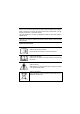
SYMBOLS USED ON THE MACHINE Tap symbol Used to indicate the solenoid valve switch Voltage symbol Used to indicate the machine's voltage switch Symbol denoting suction motor Used to indicate the suction motor switch Indicates the maximum temperature of the detergent solution Located near the solution tank inlet 6
GENERAL SAFETY REGULATIONS The regulations below must be carefully followed in order to avoid harm to the operator and damage to the machine. Read the labels on the machine carefully. Do not cover them for any reason and replace them immediately if they become damaged. The machine must be used exclusively by authorised, trained personnel. During the working of the machine, pay attention to other people and especially to children.
MACHINE PREPARATION 1. HANDLING THE PACKED MACHINE The machine is contained in specific packaging. Every pallet consists of four machines arranged on two levels. It is not possible to place more than two packages on top of each other. The overall mass for a single package is 35kg. The overall dimensions of the package are: A : 500 mm B : 500 mm C : 1150 mm 2. HOW TO UNPACK THE MACHINE 1. Open the packaging on the side indicated. 2. Take the machine out of its packaging. 3.
MACHINE PREPARATION 4. CONNECTING THE MACHINE For the connection, you must: 1. connect the extension lead to the plug on the handlebars 2. block the extension lead to the cable-holder handle in front of the handlebars 3. connect the extension lead to the wall socket ATTENTION: before connecting the extension lead to the socket, check the switches are in the off (“0”) position! 5.
MACHINE PREPARATION 7. RECOVERY TANK Check the recovery tank is correctly inserted in its housing, and that the tubes are correctly inserted in the tank elbows. Check the caps are correctly closed. 8. SOLUTION TANK Check the cap is correctly inserted in its housing, and that the vent pin is lowered (A). Check the valve is correctly engaged (B).
WORK 1. PREPARING TO WORK Before fitting the tanks, it is necessary to carry out certain operations: 1. check the switches are in the off (“0”) position 2. connect the cable to the socket 3. carry out the operations to prepare the machine 4. lower the squeegee command lever in order to start working 5. press the main switch (1) and check the green indicator light comes on 6. press the suction switch (2) and check the green indicator light comes on 7.
WORK 3. FORWARD MOVEMENTS The traction of these machines is obtained by means of the brush which, working slightly inclined, is able to drag the machine forwards. ATTENTION: when making even brief reverse movements, check the squeegee is raised.
AT THE END OF THE WORK At the end of the work, and before carrying out any type of maintenance, perform the following operations: 1. 2. 3. 4. 5. Turn off the solenoid valve switch (3) Raise the squeegee by means of the rear handle (4) Turn off the suction switch (2) Turn off the main switch (1) Disconnect the power cable from the socket 6. Bring the machine to the place provided for draining the water 7. Detach the tubes and remove the recovery tank 8.
DAILY MAINTENANCE ATTENTION: Disconnect the power cable from the mains socket before carrying out any maintenance operations. 1. CLEANING THE RECOVERY TANK 1. 2. Remove the tubes attached to the connectors of the recovery tank caps. Remove the recovery tank. ATTENTION: this operation must be carried out using gloves to protect against contact with dangerous solutions. 3. 4. 5. Remove the caps to open the tank. Clean the filter under running water. Rinse the tank and clean with a jet of water. 2.
DAILY MAINTENANCE 3. REPLACING THE SQUEEGEE RUBBERS Check the state of wear and tear of the squeegee rubbers and, if necessary, replace them. To replace them you must: 1. Raise the squeegee 2. Remove the two knobs 3. Disassemble the squeegee from its support 4. Remove the tube from the squeegee nozzle so the squeegee can be removed 5. Unscrew the knobs on the squeegee that block the rubber-pressing blades and remove them 6. Remove the rubber-pressing blades 7. Replace the rubbers 8.
PERIODIC MAINTENANCE 1. CLEANING THE SQUEEGEE TUBE Periodically, or whenever suction seems to be unsatisfactory, check the squeegee tube is not obstructed. To clean it, proceed as follows: 1. remove the tube from the sleeve on the squeegee 2. remove the other end from the recovery tank 3. wash the inside of the tube with a water jet introduced from the side where it is connected to the tank 4. reassemble the tube ATTENTION: Do not wash the tube running between the suction unit and the suction cap. 2.
TROUBLESHOOTING 1. ELECTRICAL SYSTEM SAFETY The machine is fitted with a thermal trip unit with manual reset. The brush motor is reset by resetting the thermal trip unit located beneath the handlebars. If the machine stops repeatedly in a short space of time, you must contact the Comac technical assistance centre. 2. INSUFFICIENT WATER ON THE BRUSHES 1. 2. 3. 4. 5. Check the solution tank filter is clean. Check the solenoid valve switch is on. Check the quick connection is correctly inserted.
CHOOSING AND USING THE BRUSHES POLYPROPYLENE BRUSH (PPL) Used on all types of floors. Good resistance to wear and tear, and hot water (no greater than 60°C). The Polypropylene brush is non-hygroscopic and therefore retains its characteristics even when working in wet conditions. PAD HOLDER The pad holder is recommended for cleaning shiny surfaces.
EC DECLARATION OF CONFORMITY The undersigned company: COMAC S.p.A. Via Ca’ Nova Zampieri no. 5 37057 San Giovanni Lupatoto (VR), Italy declares under its sole responsibility that the FLOOR SCRUBBER-DRYER mod. VISPA 35 E complies with the requirements of the following Directives: • 98/37/EEC: Machinery Directive • 2004/108/EC: Electromagnetic Compatibility Directive and subsequent amendments.
COMAC spa Via Cà Nova Zampieri, 5 – 37057 San Giovanni Lupatoto – Verona – ITALY Tel. +39 045 8774222 – Fax +39 045 8750303 – E-mail: com@comac.it o info@comac.it - www.comac.