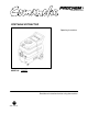
PORTABLE EXTRACTOR Operating Instructions MODELS: CM2EC Read these instructions before using the machine H 98931 03/21/05
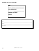
MACHINE DATA LOG/OVERVIEW MODEL _______________________________________ DATE OF PURCHASE __________________________ SERIAL NUMBER ______________________________ SALES REPRESENTATIVE # _____________________ DEALER NAME ________________________________ OPERATIONS GUIDE NUMBER ___________________ PUBLISHED __________________________________________ YOUR DEALER Name: __________________________________________________________________________________________________ Address: ____________________________________
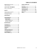
TABLE OF CONTENTS Machine Data Log/Overview. .........................2 Table of Contents ...........................................3 HOW TO USE THIS MANUAL How to use this Manual..................................1-1 SAFETY Important Safety Instructions.........................2-1 Hazard Intensity Level. ..................................2-2 Grounding Instructions...................................2-3 GROUP PARTS LIST Base Group.......................................................................
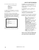
HOW TO USE THIS MANUAL This manual contains the following sections: - - HOW TO USE THIS MANUAL SAFETY OPERATIONS MAINTENANCE PARTS LIST The HOW TO USE THIS MANUAL section will tell you how to find important information for ordering correct repair parts. Parts may be ordered from authorized dealers. When placing an order for parts, the machine model and machine serial number are important. Refer to the MACHINE DATA box which is filled out during the installation of your machine.
IMPORTANT SAFETY INSTRUCTIONS When using an electrical appliance, basic precaution must always be followed, including the following: READ ALL INSTRUCTIONS BEFORE USING THIS MACHINE. ! WARNING: To reduce the risk of fire, electric shock, or injury: Use only indoors. Do not use outdoors or expose to rain. Use only as described in this manual. Use only manufacturer’s recommended components and attachments.
HAZARD INTENSITY LEVEL The following symbols are used throughout this guide as indicated in their descriptions: HAZARD INTENSITY LEVEL There are three levels of hazard intensity identified by signal words -WARNING and CAUTION and FOR SAFETY. The level of hazard intensity is determined by the following definitions: ! WARNING WARNING - Hazards or unsafe practices which COULD result in severe personal injury or death.
GROUNDING INSTRUCTIONS THIS PRODUCT IS FOR COMMERCIAL USE ONLY. ELECTRICAL: The amp, hertz, and voltage are listed on the data label found on each machine. Using voltages above or below those indicated on the data label will cause serious damage to the motors. EXTENSION CORDS: If an extension cord is used, the wire size must be at least one size larger than the power cord on the machine, and must be limited to 50 feet (15.5m) in length. GROUNDING INSTRUCTIONS: This appliance must be grounded.
TECHNICAL SPECIFICATIONS ITEM Electrical Electric Vacuum Motor Solution Pump Solution Capacity Recovery Capacity Dimensions – Weight (Empty) Dimensions - Length Dimensions - Height Dimensions - Width Power Cable 3-1 10/29/01 DIMENSION/CAPACITY 230V 50HZ DUAL 2 STAGE 100PSI 10 gal. (38L) 10 gal. (38L) 81 lbs. (37kgs) 31 in. (78.7cm) 35.5 in. (90.2cm) 17 in. (43.2cm) 25 ft. (7.
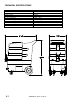
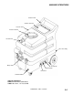
MACHINE OPERATIONS Solution Tank Solution Tank lid Vacuum Tank Vacuum Tank lid Vacuum Inlet Base Assembly Dump Valve Vacuum #2 Water Pump Vacuum #1 Solution Outlet Optional equipment: 89226 Deluxe Professional Wand 39605 Hose Asm, 1.
MACHINE OPERATIONS CLEANING & EMPTYING TANKS PRE-RUN INSPECTION 1. 2. 3. Check all fittings and connectors for proper assembly. Check all hoses for leaks. Repair or replace any damaged hoses. Check power cord(s) for any damage. If damaged, replace. EQUIPMENT SET-UP 1. 2. 3. 4. 5. 6. 7. 8. Plug power cord from machine into properly grounded wall outlet. Turn vacuum motor switch on and off to make sure there is electrical power at machine. Connect vac hose to machine.
MACHINE OPERATIONS SHUT DOWN AND STORAGE 1. 2. 3. 4. 5. Turn Switch OFF. Empty recovery tank completely and rinse several times to remove any dirt or debris that may be left behind. Drain any unused cleaning solution from solution tank and rinse with clean water to remove any suds left behind by the cleaning chemicals. NOTE: Dispose of waste in a proper manner which would not violate any Local, State or Federal law Run a small amount of clean water through pump if chemicals were used.
MAINTENANCE DAILY MAINTENANCE MONTHLY MAINTENANCE Unplug power cord(s) before servicing or making any repairs. 1. Flush the entire system, including floor tool, hand tool, etc., with 1 to 3 gallons of clean, hot water. 2. Vacuum out the solution tank. 3. Rinse tank with fresh water. Periodically inspect the recovery tank and decontaminate if necessary, using a Hospital Grade Virucide or a 1-10 bleach to water solution. Wastewater should be disposed of properly. 4.
MAINTENANCE Vacuum Motor Carbon Brushes Replacement (Ametek) End Cap Carbon Brushes WARNING: The green ground wire must be attached for safe operation. See wiring diagram. Note: When replacing carbon brushes loosen wire terminal BEFORE removing screws on bracket. Only qualified maintenance personnel are to perform the following repairs. SOLUTION PUMP REPLACEMENT 1. 2. 3. 4. Wire Terminal 5. 6. Turn off all switches and unplug the machine. Unlatch the recovery tank from the base.
MAINTENANCE PUMP REPLACEMENT KITS 100 PSI - FLOJET (65220) DIAPHRAGM 29219 PUMP HEAD VALVE ASM 65204 MOTOR 53246 84166 PUMP REPLACEMENT KITS 100 PSI-SHURFLO (250-64B) PRIOR TO SN# 1000107206 250-67 Switch Asm Pump Head Replacement 65187 4-3 Bypass Valve Asm 84161 COMANCHE 98931 04/07/03 Diaphragm 29206
MAINTENANCE PRESSURE REGULATOR For best results with the pressure regulator, we recommend that you clean and lubricate the piston and u-cup with Superlube lubricant monthly or when pressure drop seems excessive. 1. Turn unit off before lubricating. 2. Remove cap, spring and spring retainer plate. 3. With fingertips remove piston and u-cup. 4. Wipe piston and u-cup clean of any film or scale. 5. Lubricate the piston and u-cup with Superlube. 6. Reassemble regulator. 7.
TROUBLESHOOTING PROBLEM Loss of Power Electrical shock CAUSE SOLUTION Dead electrical circuit Faulty power cord Equipment not grounding Receptacle not grounded Check building circuit breaker or fuse box.
THIS PAGE LEFT BLANK INTENTIONALLY COMANCHE 98931 04/07/03 4-6
BASE GROUP 3 2 15 2 3 20 3 1 2 21 3 19 4 18 5 17 22 16 15 6 14 13 12 3 8 7 11 3 9 8 5-1 COMANCHE 98931 12/06/01 10
BASE GROUP PARTS LIST REF 1 2 3 4 5 6 7 8 9 10 11 12 13 14 15 16 17 18 19 20 21 22 PART NO. 57090 70015 87013 87095 140-05 280-02 040-03 57245 87080 57196 040-06 56-502068 32-900195 70595 50-501858 70532 08068 20008 280-03 46-802536 33-901006 57054 QTY 3 15 30 4 2 4 2 15 2 2 2 1 3 1 1 3 1 1 1 1 1 1 DESCRIPTION NUT, 10-32 HEX NYLOCK SS SCR, 1/4-20 X 3/4 HHCS SS NP WASHER, 1/4 ID X 5/8 OD SS WASHER, #10 FLAT PLTD DRAW PULL LATCH STD. RIVET AL.
LABEL & STRAP GROUP 3 4 2 1 5-3 COMANCHE 98931 12/06/01
LABEL GROUP PARTS LIST REF PART NO. QTY 1 2 3 4 500568 500531 320-05 500009 1 2 1 1 DESCRIPTION SERIAL NO. FROM NOTES: LABEL, COMANCHE MAIN LABEL, PROCHEM LOGO 6 X 1.
PUMP GROUP 20 28 21 19 TO SOLUTION TANK 17 1 22 18 23 (A) 2 17 1 25 27 1 22 10 1 16 4 24 26 3 15 1 5 14 1 (A) 9 6 13 7 12 9 10 8 11 5-5 COMANCHE 98931 05/02/02
PUMP – GROUP PARTS LIST REF PART NO.
RECOVERY TANK GROUP 1 16 2 15 14 13 12 3 9 4 5 11 3 6 8 7 5-7 COMANCHE 98931 03/21/05
RECOVERY TANK GROUP PARTS LIST REF PART NO. QTY DESCRIPTION 1 2 3 4 5 6 7 8 9 10 11 12 13 14 15 16 090-12A 78489 35256 260-33 140-05 370-06A 31032 70683 87257 OPEN 31002 81491 75378 35255 260-64A 70546 1 1 2 1 2 1 1 4 1 FLOAT CAGE ASSY COMPLETE SLIP VAC, STACK ASM, COMANCHE GASKET, DUMP VALVE HOSEBARB, 1.5 MPT X 1.5 DRAW PULL LATCH STD. DUMP VALVE 1-1/2 M THREAD ELBOW, 1.5 FS X FS 45D PVC SCR, 10-32 X 3/8 PPHMS SS NP WASHER, HOSEBARB 1 4 1 1 1 6 ELBOW, 1.5 FPT X FS PVC SET SCR, 5/16-18 X 1.
SOLUTION TANK GROUP 14 1 2 3 13 12 4 11 5 10 9 6 8 7 5-9 COMANCHE 98931 12/06/01
SOLUTION TANK – GROUP PARTS LIST REF PART NO.
VACUUM MOTOR GROUP 6 9 3 1 1 2 4 5 4 7 5 11 9 10 1 5-11 COMMANCHE 98931 06/14/03 8
VACUUM MOTOR GROUP PARTS LIST REF 1 2 3 4 5 6 7 8 9 10 11 PART NO. 87013 70011 43-807517 065-92 35166 70663 57245 56-502084 360-06 140216 140688 57105 70814 QTY 9 3 1 6 2 3 3 1 2 3 3 DESCRIPTION WASHER, 1/4 ID X 5/8 OD SS SCR, 1/4-20 X 5/8 HHCS SS GASKET, VAC MTG. VAC SPACER 2 1/4 GASKET, VAC MOTOR SCR, 1/4-20 X 3 ¼ HHCS PLT NUT, 1/4-20 HEX NYLOCK SS BRKT, VAC MOUNT, DUAL 2 STG VAC MOTOR, 230V 5.4 2ST TD BRUSH SET, 230V VAC AMETEK BRUSH SET, 230V VAC WINDSOR NUT, 1/4-20 W/STAR WASHER STUD, 1/4-20 X 4.
WIRING DIAGRAM 5-13 COMANCHE 98931 12/06/01
NOTES NOTES: COMANCHE 98931 05/02/02 5-14
LIMITED WARRANTY PROCHEM warrants your new machine to be free of defects in material and workmanship. This warranty shall extend to the designated parts for the specific time period listed from the date of delivery to the user. If PROCHEM receives notice of such defects during warranty period, PROCHEM will either, at it’s option, repair or replace products which prove to be defective. Any local or distant transportation, related service labor and diagnostic calls are not included.