
User's Manual

INSTALLATION GUIDE FOR UHF DAS
ENU STATUS : 1-0-0
Copyright - refer to title page
Page 15
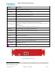
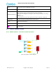
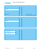
Identifier
Descriptions
OP1/OP2
Optical ports
UL1
Connect IN1 of MU (Master Unit)
DL1
Connect OUT1 of MU (Master Unit)
UL2
Connect IN1 of MU (Slave Unit), this port is only used when the backup function is
used
DL2
Connect OUT1 of MU (Slave Unit), this port is only used when the backup function is
used
UL_E
Connect to UL1 of next EU for cascade connection
DL_E
Connect to DL1 of next EU for cascade connection
Ground terminal
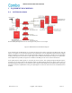
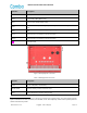
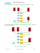
Figure 7: RU Equipment Connectors
Table 3: RU Equipment Connectors
Identifier
Descriptions
Power
1
Power cable connector for a pre-installed power cord for connection to DC
(e.g. DC -48V, Max, current is 8A).
ALM1/ALM2
Connector for Dry contact or External alarm
AUX
Used for Equipment extension wiring routing
1
The voltage identification is a variant due to electricity system diversity of global regions. The power cable connector
might be identified for AC 110V, AC 220V, AC 110V/220V, or DC -48V respectively. Please refer to specific product or
contact local sales if any doubt.