
User's Manual

INSTALLATION GUIDE FOR UHF DAS
ENU STATUS : 1-0-0
Copyright - refer to title page
Page 30
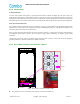
⚫ Connect the negative pole of the external DC power supply to the terminal "-48V".
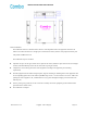
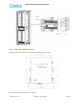
3.3.10 DC POWER AND MONITOR CABLE CONNECTION BETWEEN MU AND EU
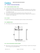
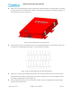
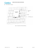
Figure 20: DC power and Monitor cable connection
⚫ The power supply of the Expansion Unit is DC24V-DC48V, which can be directly supplied by the MU or DC48V
independently. When powered by the MU, the main MU power supply line connection: VOUT+→IN1+, VOUT-
→IN1-; the standby MU power supply line connection: VOUT+→IN2+, VOUT-→IN2-;
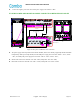
⚫ Switch Cable connection: main MU→EU: SW→SW1; backup MU→EU: SW→SW2;
⚫ RJ45 Cable connection: main MU→EU: FOU→AUX1; backup MU→EU: FOU→AUX2.
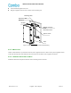
RJ45 Cable
SW Cable
Power cable
SW of MU(Backup
Unit)
MU(Main Unit)
EU
MU(Backup Unit)