CRITICALPOINT ANTENNA MONITORING SYSTEM USER MANUAL QE: 1-0-1
Comba Telecom Ltd. The information contained herein is the responsibility of and is approved by the following, to whom all enquiries should be directed: This is an unpublished work the copyright in which vests in Comba International ("Comba"). All rights reserved. The information contained herein is confidential and the property of Comba and is supplied without liability for errors or omissions. No part may be reproduced, disclosed or used except as authorized by contract or other written permission.
INSTALLATION GUIDE FOR RX-7W22 0.1 CONTENTS Section Page 0.1 0.2 0.3 0.4 0.5 2 CONTENTS....................................................................................................................................... 3 INDEX TO FIGURES AND TABLES ............................................................................................. 4 HISTORY ...........................................................................................................................................
INSTALLATION GUIDE FOR RX-7W22 0.2 INDEX TO FIGURES AND TABLES Figure 1: CriticalPoint Antenna Monitoring Solution System Block Diagram ......................................................8 Figure 2: MCU (Main Control Unit) Block Diagram .............................................................................................9 Figure 3: Equipment Connectors .....................................................................................................................
INSTALLATION GUIDE FOR RX-7W22 0.3 HISTORY Change No.
INSTALLATION GUIDE FOR RX-7W22 0.
INSTALLATION GUIDE FOR RX-7W22 0.5 SAFETY NOTICES AND ADMONISHMENTS This document contains safety notices in accordance with appropriate standards. In the interests of conformity with the territory standards for the country concerned, the equivalent territorial admonishments are also shown. Any installation, adjustment, maintenance and repair of the equipment must only be carried out by trained, authorized personnel. At all times, personnel must comply with any safety notices and instructions.
INSTALLATION GUIDE FOR RX-7W22 1 GENERAL INFORMATION The CriticalPoint Antenna Monitoring System consists of the Main Control Unit (MCU) and monitoring tags which are easily installed on the service antennas. The system utilizes RFID (Radio Frequency Identification) technology, that is incorporated into the DAS (Distributed Antenna System), to monitor the link status of the entire passive network.
INSTALLATION GUIDE FOR RX-7W22 2 EQUIPMENT DESCRIPTION 2.1 MCU (MAIN CONTROL UNIT) BLOCK DIAGRAM Figure 2: MCU (Main Control Unit) Block Diagram MCU generates a pilot signal at 910MHz or 915MHz, combines the RF signal from BDA/Signal Booster through the combiner and transmit the combined signal to each of the antenna, the RFID tags in the antenna will be energized by the pilot signal and send a response back to the MCU.
INSTALLATION GUIDE FOR RX-7W22 3 INSTALLATION 3.1 WARNINGS AND ALERTS Radio Frequency Energies There may be situations, particularly for workplace environments near high-powered RF sources, where recommended limits for safe exposure of human beings to RF energy could be exceeded. In such cases, restrictive measures or actions may be necessary to ensure the safe use of RF energy. High Voltage The equipment has been designed and constructed to prevent, as far as reasonably practicable danger.
INSTALLATION GUIDE FOR RX-7W22 3.2 EQUIPMENT CONNECTION 3.2.1 EQUIPMENT CONNECTORS Figure 3: Equipment Connectors Table 1: Equipment Connectors Identifier Descriptions DC48V Power cable connector for a pre-installed power cord for connection to DC (48V) RF IN N Female, connect to BDA or Signal Booster MT or Service port RF OUT N Female, connect to the passive system to the antennas ETH RJ45 Connector for local WEB GUI connection.
INSTALLATION GUIDE FOR RX-7W22 3.2.2 RF CABLE CONNECTION AMS RF cables connection is as follows: ⚫ RF IN port → connect to BDA or Signal Booster’ MT or Service port ⚫ PF OUT port → connect to the passive system to the antennas 3.2.3 POWER CONNECTION Connect the power cord to the DC48V power source ⚫ RED → connect to Positive ⚫ BLUE → connect to Negative 3.2.4 ETHERNET CONNECTION Establish an Ethernet connection using the ‘ETH’ port located on the panel. 3.2.
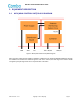
INSTALLATION GUIDE FOR RX-7W22 4 TAG INSTALLATION Use addressable antenna: ⚫ IXD-360H04YJN-ADR: Low profile, Ceiling Mount, 380-2700MHz, H Pol, 360°, 2.0/2.2/4.5dBi ⚫ IXD-360H04MJN-ADR: Low profile, Ceiling Mount, 698-2700MHz, H Pol, 360°, 2.2/3.5/4.5dBi Or put the RFID tags on the antenna emission surface: ⚫ These tags should be installed on in-building services antennas and the gain for these antennas shall not be exceeding 12.5dBi gain.
INSTALLATION GUIDE FOR RX-7W22 5 WEB GUI The AMS can be monitored and controlled via the WEB GUI; use the following guide to finish system parameter setting and commissioning. 5.1 WEB GUI CONNECTION Step 1: Connect the ETH port to the PC RJ45 port to set up a physical connection. Step 2: Manually change the IP address of the PC to be 192.168.1.100/255.255.255.0 Step 3: Open a browser (Chrome or Firefox), connect 127.0.0.1:8080/web_Antenna for login 5.2 WEB GUI INTRODUCTION 5.2.
INSTALLATION GUIDE FOR RX-7W22 5.2.
INSTALLATION GUIDE FOR RX-7W22 5.2.
INSTALLATION GUIDE FOR RX-7W22 5.2.
INSTALLATION GUIDE FOR RX-7W22 5.2.
INSTALLATION GUIDE FOR RX-7W22 5.2.
INSTALLATION GUIDE FOR RX-7W22 6 APPENDICES 6.
INSTALLATION GUIDE FOR RX-7W22 ENU STATUS : 1-0-2 Copyright - refer to title page Page 21