Automotive Winch Thank you for purchasing a Winch. This manual covers operation and maintenance of the winch. All information in this publication is based on the latest production information available at the time of printing. We reserve the right to make changes without notice because of continued product improvement. The winch has been designed to give safe and dependable service if operated according to the instructions.
Control Indicator Guide There are three control modules of the Comeup automotive winches. All are similar in setup, but have differing responses in regards to their control type. Determine which model you have and refer to the charts for you particular models signalling of its condition through LED’s and buzzer. Wired Remote Control Module Available Winches Seal 9.5i/9.
Control Indicator Guide Wired Remote Control Module on the dual control modules Available Winch Seal 9.5rsi LED & Buzzer LEDs and buzzer on the bridge control box Left LED Right LED Buzzer LEDs on the remote control Plug in Connector Green X X Green Cable In/Out Operation Green X Green Red X X 2 short Beeps every 5 seconds Motor Overheating Warning Plug out Connector Red LED turns off Seal 9.5rs / 12.5rs (Buzzer in the control box) Available Winches Remarks: 1.
Control Indicator Guide b. Press and hold the Power Button for about 5 seconds, then the LED Indicator illuminates Green permanently. c. Press either Cable In Button or Cable Out Button for programming. d. After the completion of programming, the buzzer sounds a long beep lasting for 5 seconds. For Seal 9.5rsi winch, the Right LED turns off and the Left LED illuminates Green permanently. e.
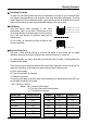
Control Indicator Guide Battery Recommendations and lead size A fully charged battery and good connections are essential for the proper operation of your winch. The minimum requirement for battery is 650 cold cranking amp. The voltage drop for the winch motor must not exceed 10% of the nominal voltage of 12/24V DC. The battery lead shall be 2 gauge with 1.83 m in length at most, otherwise a considerable voltage drop will be happened. Cable-in / Cable-out Operation For Wired Remote Control 1.
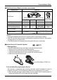
Mounting Guide Clutch Function 1. 2. 3. 4. 5. 6. 7. The clutch allows rapid pay-out of the wire/synthetic rope for hooking onto a load or anchor points and is operated by a clutch T-handle. The clutch T-handle must be in the “Engaged” position before winching. To disengage, lift the clutch T-handle up and turn it at the proper angle mentioned in the mounting configurations chart below in a counter-clockwise direction to the “Disengaged” position. Wire/synthetic rope can now free spool off the drum.
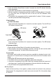
Mounting Guide Clutch Repositioning Change the position of the Free-Spool T-handle according to the following steps. 1. Loosen and release the bolts on the brake rear cover for separating the brake rear cover away. 2. Loosen and release the bolts on the gearbox away for separating the gear box away (Only for Seal series winches). 3. Rotate the gearbox by a proper angle increments mentioned on the below chart to the required position. 4. Re-assembly the gearbox and rear brake cover.
Safety Requirements In some cases, the operator of a winch may be required to have qualifications according to applicable laws and ordinances. Check safety and environmental conditions prior to and during use. Only use correctly rated wire/synthetic rope in construction, strength. Inspect for damage and/or defects before use. Don’t use an unsuitable hook and snatch block for rope. The operator must remain with the winch during operation. The winch duty rating is S3 (intermittent-periodic).
Winching Principles Calculating Fleet Angle To obtain the best wire/synthetic rope service, the direction of pull will be on a horizontal within ±15 degrees and perpendicular to be centerline of the winch drum within ±5 degrees. If the fleet angle is bigger than the recommended angles, a good spooling cannot be obtained as the rope will spoon onto one side of the rope drum and possible damage to the rope or winch. Load Rating Top layer (Max.
Winching Principles For example, if a vehicle weighing 3,000 kg is winched up an incline by 100% on the marsh road, the above formula would be used as follows: Where Wt: 3,000 kg, S: 0.52 G: 0.71 RPF = (Wt X S) + (Wt X G) = (3,000 kg X 0.52) + (3,000 kg X 0.71) = 1,560 kg + 2,130 kg = 3,690 kg of effect required to recover the vehicle.
Accessories Roller Fairlead The use of 4 ways roller fairlead can eliminate the contacting friction because the fairlead rollers contact with the wire rope. But the fairlead does not insure the wire rope will wind onto the drum in an orderly manner. The proper fleet angle within 15° must be maintained for the wire rope to wind onto the drum in an orderly manner. If the proper fleet angle is not maintained, it can result in damage to the winch and wire rope.
Winching Procedures Preparation before Winching 1). Connect the remote control Always disconnect the remote control when not in use. Always have the remote control kept free from winch, wire/synthetic rope and roller/hawse fairlead. 2). Disengage clutch function 2 Lift the clutch T-handle up and turn it at 90° counter-clockwise rotation to the “Disengaged” position, rope can now clutch off the drum. 3).
Winching Procedures 3). Secure anchor point It is very important that an anchor point is strong enough to hold the load while winching. Do not wrap the rope around the load and back onto itself. Always use a strap to ensure that the wire/synthetic rope does not fray or kink. P R N D 2 1 4). Setting the vehicle engine The recovery vehicle engine should be running to provide maximum power to the winch.
Winching Procedures X Precaution while winching Make sure the rope is wound on the drum evenly. A tightly spiraled pig-tailed rope will damage the rope, shorten its life. Always keep clear of winch, rope, hook, and roller/hawse fairlead during winching. Keep winching area clear. Do not allow people to remain in the area while winching. Never guide a wire/synthetic rope onto the drum with your hand, use a hand saver strap. Avoid remote control cord from touching the wire/synthetic rope.
Maintenance Wire Rope Replacement Do not wind out past the red paint section of the rope to secure the anchorage of the rope on the drum. 1). Disengage the clutch T-handle. 2). Spool the entire rope, and then remove it from the drum. 3). Place the replacement rope through the roller fairlead opening, pass below the drum and insert it into the hole on the drum core. Tighten the set-screw downwards to secure the wire rope. 4).
Maintenance Tip for prolonging the life of Synthetic rope 1. Regular maintenance and periodically check the rope for damage or wear 2. Since too much abrasion can damage or weaken your synthetic rope, protect your rope from rubbing against sharp objects or edge 3. An aluminum hawse fairlead is highly recommended since it has no sharp edges and resists damage more easily than a roller fairlead 4. Keeping your synthetic rope clean and dry. To clean it after a muddy ride, spool out the 5.
Maintenance CE Mark Warning • This is a Class B product, in a domestic environment, this product may cause radio interference, in which case the user may be required to take adequate measures. FCC and Industry Canada (IC) Warning: • This device complies with Part 15 of the FCC Rules. Operation is subject to the following two conditions: (1) This device may not cause harmful interference, and (2) this device must accept any interference received, including interference that may cause undesired operation.
Maintenance X Maintenance Schedule Classification of check Daily Checking method Item Periodical Checking reference Monthly Quarterly Installation Mounting bolts & Bolt tension & Existence of abnormalities alignment wear c Working c c Remote Wearing in contact points control Manual Reasonable actuation Visual Free of wear or damage c LED lights red Visual LED light green c Broken strands Visual, i Visual, measuring Less than 10% 7% of nominal diameter max Fastening condition of end Vi
Trouble Shooting If the winch fails to operate after several attempt, or if there is any fault whilst operation: Symptom Possible Cause Cut circuit Weak battery Damaged over-load protector(option) Winch will not Bad connection of wiring Damaged contactor operate Cut circuit on switch Damaged motor or carbon brush. Poor or lost connections to motor Broken wiring or bad connections Motor runs in one Damaged or stuck contactor direction.
Automotive Winch Limited Lifetime Warranty for Mechanical Components Limited One (1) Year Warranty for Electrical Components WARRANTY Comeup Industries Inc. (COMEUP) warrants to the original purchaser that the mechanical components of the COMEUP Automotive Winch will be free of defects in material and workmanship for the lifetime of the winch and the electrical components will be free of defects in material and workmanship for a period of one (1) year from the original date of purchase.