
Product Overview
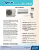

‘DV’ Series
Single Zone Ductless Mini-Splits Systems
Cooling Only Heat Pump Models
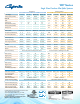
FEATURES DVC09SF-0 DVC12SF-0 DVC18SF-1 DVC24SF-1 DVH09SF-0 DVH12SF-0 DVH18SF-1 DVH24SF-1
Power Supply 115-1-60 115-1-60 208/230-1-60 208/230-1-60 115-1-60 115-1-60 208/230-1-60 208/230-1-60
Cooling Capacity (BTUH) 9,000 12,000 18,000 23,000 9,000 12,000 18,000 24,000
SEER/ EER 16.0/11.0 16.5/10.0 16.0/10.5 17.0/10.6 17.0/11.5 17.2/10.5 17.7/11.0 16.0/9.0
HSPF - - - - 9.0 9.0 9.8 9.0
Cooling Amps 7.1 10.4 7.5 9.4 7 10.4 7.2 11.2
Dehumidication (Pts/Hr.) 2 2.5 3.8 7.2 2.1 2.5 3.8 5.5
Heating Capacity (BTUH) - - - - 9,500 12,000 18,000 24,000
Heating Amps - - - - 8.4 10 8.5 10.7
-INDOOR UNIT
Air ow (CFM) 242/198/142 280/252/171 388/265/224 618/471/324 247/177/129 294/212/141 388/265/224 589/459/335
Fan Speeds (Cool/Heat/Fan) 3/ - /3 3/ - /3 3/ - /3 3/ - /3 3/3/3 3/3/3
3/3/3 3/3/3
Sound Level (dBa) H-M-L
37/-/24 38.5/-/24.5 45/39/33 50/-/38 36.5/-/22 38/-/24 44/-/26.5 45.5/-/33
AIR DIRECTION
Vertical Adjustment Remote Remote Remote Remote Remote Remote Remote Remote
Horizontal (left/right) Manual Manual Manual Manual Manual Manual Manual Manual
Auto Swing Up and Down Standard Standard Standard Standard Standard Standard Standard Standard
INDICATOR LAMPS
ON/OFF Standard Standard Standard Standard Standard Standard Standard Standard
24 Hr. Timer/Sleep Mode Standard Standard Standard Standard Standard Standard Standard Standard
Defrost N/A N/A N/A N/A Standard Standard Standard Standard
Temperature Setting Remote Temperature Set Range: 62°F to 86°F Remote Temperature Set Range: 62°F to 86°F
INDOOR UNIT DIMENSIONS
Width (inches) 28
7
/
16
31
9
/
16
38 42
9
/
16
28
7
/
16
31
9
/
16
38
42
9
/
16
Height (inches) 11
7
/
16
11
11
/
16
12
9
/
16
13
3
/
16
11
7
/
16
11
11
/
16
12
9
/
16
13
3
/
16
Depth (inches) 7
3
/
8
7
7
/
16
8
1
/
2
8
15
/
16
7
3
/
8
7
7
/
16
8
1
/
2
8
15
/
16
Net Wt/Shipping Wt (lbs.) 15.9/19.8 16.3/20.3 24.7/28 28.9/36.8 16.5/20.9 18.7/22.5 26.0/34.2 29.1/37.0
OUTDOOR UNIT DIMENSIONS
Width (inches) 30
5
/
16
30
5
/
16
31
1
/
2
33
5
/
16
30
5
/
16
30
5
/
16
31
1
/
2
36
Height (inches) 21
7
/
8
21
7
/
8
21
13
/
16
27
5
/
8
21
7
/
8
21
7
/
8
21
13
/
16
23
15
/
16
Depth (inches) 11
13
/
16
11
13
/
16
13
1
/
8
14
5
/
16
11
13
/
16
11
13
/
16
13
1
/
8
14
3
/
16
Net Wt/Shipping Wt (lbs.) 63.9/69.4 65.0/71.7 68.3/72.8 98.8/110.7
63.9/69.4 65.0/70.5 80.5/87.1
136.7/147.3
ELECTRICAL DATA OUTDOOR UNIT*
Main Power Connection Outdoor Unit Outdoor Unit Outdoor Unit Outdoor Unit Outdoor Unit Outdoor Unit Outdoor Unit Outdoor Unit
Min. Circuit Ampacity 15A 15A 11A 16A 15 15 15 18
Max. Fuse/HACR
Circuit Breaker
20A 20A 15A 25A 20 20 20 25
Recommended Indoor/
Outdoor Connecting Cable*
14 AWG / 4 conductor
600V THHN unshielded bare copper
14 AWG / 4 conductor
600V THHN unshielded bare copper
LINE SETS O.D. (inch)
Liquid Connection (are) (inch) 1/4 1/4 1/4 3/8 1/4 1/4 1/4 3/8
Suction Connection (are) (inch) 3/8 1/2 1/2 5/8 3/8 1/2 1/2 5/8
Maximum Line Set Length
1
82 feet 82 feet 98 feet 98 feet 82 feet 82 feet 98 feet 98 feet
Maximum Elevation (outdoor)
2
33 feet 33 feet 66 feet 66 feet 33 feet 33 feet 66 feet 66 feet
* Always follow local, state and national electrical codes.
1
Min. 10 ft. line set recommended.
2
Oil traps should be installed every 16.5 to 23
feet (5-7m) when the outdoor unit is installed
above the indoor unit.
Design, specications and performance data
subject to change without notice.
C US