INSTALLATION MANUAL UltraV Series Outdoor Units Models A-VMH18DU-1 A-VMH28TU-1 A-VMH36QU-1 517.787.2100 • www.marsdelivers.
Installation Manual - A-VMH18DU,28TU,36QU-1 Table of Contents Installation Manual 1 Accessories ......................................................... 4 2 Safety Precautions ..................................... 5 3 Installation Overview ............................. 8 4 Installation Diagram .............................. 9 5 Specifications ................................................. 10 6 Outdoor Unit Installation ...........................
Installation Manual - A-VMH18DU,28TU,36QU-1 7 Refrigerant Piping Connection ............... L 14 N 9 Air Evacuation ........................................... 23 Evacuation Instructions ......................... Note on Adding Refrigerant ............... Safety And Leakage Check .................. 23 10 Test Run....................................................... 8 Wiring..................................................... 17 Outdoor Unit Wiring ................... Wiring Figure ......
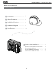
Installation Manual - A-VMH18DU,28TU,36QU-1 1 Accessories The air conditioning system comes with the following accessories. Use all of the installation parts and accessories to install the air conditioner. Improper installation may result in water leakage, electrical shock and fire, or equipment failure. Name Shape Quantity Plastic expansion sheath 1 5-8 (depending on models) Self-Tapping Screw A ST3.
Installation Manual - A-VMH18DU,28TU,36QU-1 2 Safety Precautions Read Safety Precautions Before Installation Incorrect installation due to ignoring instructions can cause serious damage or injury. The seriousness of potential damage or injuries is classified as either a WARNING or CAUTION. WARNING Failure to observe a warning may result in death. The appliance must be installed in accordance with national regulations. Failure to observe a caution may result in injury or equipment damage.
Installation Manual - A-VMH18DU,28TU,36QU-1 WARNING • The appliance disconnection must be incorporated with an all-pole disconnection device using hard wiring in accordance with electrical codes. • Any person who is involved with working on or breaking into a refrigerant circuit should hold a current valid certificate from an industry-accredited assessment authority, which authorizes their competence to handle refrigerants safely in accordance with an industry recognized assessment specification.
Installation Manual - A-VMH18DU,28TU,36QU-1 Note about Fluorinated Gasses 1. This air-conditioning unit contains fluorinated gasses. For specific information on the type of gas and the amount, please refer to the relevant label on the unit itself. 2. Installation, service, maintenance and repair of this unit must be performed by a certified technician. 3. Product uninstallation and recycling must be performed by a certified technician. 4.
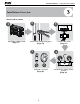
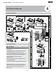
Installation Manual - A-VMH18DU,28TU,36QU-1 3 Installation Overview INSTALLATION ORDER 1 Install the outdoor unit (Page 11) 2 3 Connect the refrigerant pipes (Page 14) 5 L N Connect the wires (Page 17) 4 MC Perform a test run (Page 26) 8 MC Evacuate the refrigeration system (Page 23)
Installation Manual - A-VMH18DU,28TU,36QU-1 4 Installation Diagram Installation Diagram Mor e th 4 Mor e th an 5 " 3 2 an 5 " 1 More than 6" Air-break Switch Installation plate Mor e than 5 Clip anchor " Air-break Switch Remote controller holder 1 2 Drainage Pipe 24" 543 More 12" than 5" 5 12" 80" Outdoor Unit Power Cable The maximum amount of the connection cables is 5. This section is for reference only. 24 " (1) 6" Mounting screw ST3.
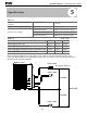
Installation Manual - A-VMH18DU,28TU,36QU-1 5 Specifications Table 5.1 Number of units that can be used together Compressor stop/start frequency Power source voltage Connected units 1-4 units Stop time 3 min or more voltage fluctuation within ±10% of rated voltage voltage drop during start within ±15% of rated voltage interval unbalance within ±3% of rated voltage Table 5.2 Unit: m/ft. A-VMH18DU-1 A-VMH28TU-1 A-VMH36QU-1 Max. length for all rooms 40/131 60/197 80/262 Max.
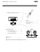
Installation Manual - A-VMH18DU,28TU,36QU-1 6 Outdoor Unit Installation √ Outdoor Unit Installation Instructions √ Step 1: Select installation location. The outdoor unit should be installed in a location that meets the following requirements: √ Place the outdoor unit as close to the indoor unit as possible. √ Ensure that there is enough room for installation and maintenance. √ The air inlet and outlet must not be obstructed or exposed to strong wind.
Installation Manual - A-VMH18DU,28TU,36QU-1 Split Type Outdoor Unit (Refer to Fig 6.4, 6.5, 6.6, 6.10 and Table 6.1) Table 6.1: Length Specifications of Split Type Outdoor Unit unit: mm(inch) Outdoor Unit Dimensions H W Fig. 6.4 W Mounting Dimensions Distance A WxHxD Distance B 760x590x285 (29.9x23.2x11.2) 530 (20.85) 290 (11.4) 810x558x310 (31.9x22x12.2) 549 (21.6) 325 (12.8) 845x700x320 (33.27x27.5x12.6) 560 (22) 335 (13.2) 900x860x315 (35.4x33.85x12.4) 590 (23.2) 333 (13.
Installation Manual - A-VMH18DU,28TU,36QU-1 60 cm / 23.6” above NOTE: The minimum distance between the outdoor unit and walls described in the installation guide does not apply to airtight rooms. Be sure to keep the unit unobstructed in at least two of the three directions (M, N, P) (See Fig. 6.8) 30 cm / 11.8 ” on M 30 cm ” 1.8 /1 rom ck ba ll wa f m 2 8” /7 left / 23.
Installation Manual - A-VMH18DU,28TU,36QU-1 7 Refrigerant Piping Connection Step1: Cut pipes Safety Precautions WARNING • All field piping must be completed by a licensed technician and must comply with the local and national regulations. • When the air conditioner is installed in a small room, measures must be taken to prevent the refrigerant concentration in the room from exceeding the safety limit in the event of refrigerant leakage.
Installation Manual - A-VMH18DU,28TU,36QU-1 Pipe Table 7.1: PIPING EXTENSION BEYOND FLARE FORM Reamer Pipe gauge Point down Tightening torque Flare dimension (A) (Unit: mm/Inch) Min. Fig. 7.2 Step 3: Flare pipe ends Proper flaring is essential to achieve an airtight seal. 1. After removing burrs from cut pipe, seal the ends with PVC tape to prevent foreign materials from entering the pipe. 2. Sheath the pipe with insulating material. 3. Place flare nuts on both ends of pipe.
Installation Manual - A-VMH18DU,28TU,36QU-1 NOTE: Use both a spanner and a torque wrench when connecting or disconnecting pipes to/from the unit. 7. Thread this pipeline through the wall and connect it to the outdoor unit. 8. Insulate all the piping, including the valves of the outdoor unit. 9. Open the stop valves of the outdoor unit to start the flow of the refrigerant between the indoor and outdoor unit. CAUTION Check to make sure there is no refrigerant leak after completing the installation work.
Installation Manual - A-VMH18DU,28TU,36QU-1 8 Wiring Safety Precautions Follow these instructions to prevent distortion when the compressor starts: WARNING • • • • • • • • Be sure to disconnect the power supply before working on the unit. All electrical wiring must be done according to local and national regulations. Electrical wiring must be done by a qualified technician. Improper connections may cause electrical malfunction, injury and fire.
Installation Manual - A-VMH18DU,28TU,36QU-1 3. Connect the u-lugs to the terminals Match the wire colors/labels with the labels on the terminal block, and firmly screw the u-lug of each wire to its corresponding terminal. 4. Clamp down the cable with designated cable clamp. 5. Insulate unused wires with electrical tape. Keep them away from any electrical or metal parts. 6. Reinstall the cover of the electric control box. b.
Installation Manual - A-VMH18DU,28TU,36QU-1 Wiring Figure CAUTION Connect the connective cables to the terminals, as identified, with their matching numbers on the terminal block of the indoor and outdoor units. For example, in the US models shown in the following diagram, Terminal L1(A) of the outdoor unit must connect with terminal L1 on the indoor unit. NOTE: Refer to the following figures if end-users wish to perform their own wiring.
Installation Manual - A-VMH18DU,28TU,36QU-1 L L(A) N(A) S(A) N L(B) N(B) S(B) TO B TO A Model I POWER SUPPLY OPTIONAL OPTIONAL Model H POWER SUPPLY OPTIONAL TO B OPTIONAL B N S(1) S(B) N(B) L(B) L OPTIONAL TO Y/G OPTIONAL A Y/G S(2) S(A) N(A) L(A) N S(1) S(B) N(B) L(B) L OPTIONAL OPTIONAL OPTIONAL TO POWER SUPPLY S(2) S(A) N(A) L(A) TO A Model J NOTE: Please refer to the following figures if end-users wish to perform their own wiring.
Installation Manual - A-VMH18DU,28TU,36QU-1 One-four models: OPTIONAL OPTIONAL OPTIONAL OPTIONAL OPTIONAL 21 OPTIONAL Model F Model E OPTIONAL POWER OPTIONAL OPTIONAL OPTIONAL OPTIONAL OPTIONAL OPTIONAL OPTIONAL OPTIONAL SUPPLY TO B Y/G A TO Y/G B TO Y/G A TO Y/G L(D) N(D) S(D) L(C) N(C) S(C) L(B) N(B) S(B) L(A) N(A) S(A) N L OPTIONAL OPTIONAL OPTIONAL OPTIONAL OPTIONAL OPTIONAL OPTIONAL OPTIONAL Model D Model C OPTIONAL OPTIONAL OPTIONAL OPTIONAL OPTIONAL OPTIONAL OP
Installation Manual - A-VMH18DU,28TU,36QU-1 CAUTION After confirmation of the above conditions, follow these guidelines when performing wiring: • Always have an individual power circuit specifically for the air conditioner. Always follow the circuit diagram posted on the inside of the control cover. • Screws fastening the wiring in the casing of electrical fittings may come loose during transportation. Because loose screws may cause wire burn-out, check that the screws are tightly fastened.
Installation Manual - A-VMH18DU,28TU,36QU-1 9 Air Evacuation Safety Precautions CAUTION • Use a vacuum pump with a gauge reading lower than -0.1MPa and an air discharge capacity above 40L/min. • The outdoor unit does not need vacuuming. DO NOT open the outdoor unit’s gas and liquid stop valves. • Ensure that the Compound Meter reads -0.1MPa or below after 2 hours. If after three hours of operation and the gauge reading is still above -0.1MPa, check if there is a gas leak or water inside the pipe.
Installation Manual - A-VMH18DU,28TU,36QU-1 Note On Adding Refrigerant CAUTION • Refrigerant charging must be performed after wiring, vacuuming, and the leak testing. • DO NOT exceed the maximum allowable quantity of refrigerant or overcharge the system. Doing so can damage the unit or impact it’s functioning. • Charging with unsuitable substances may cause explosions or accidents. Ensure that the appropriate refrigerant is used. • Refrigerant containers must be opened slowly.
Installation Manual - A-VMH18DU,28TU,36QU-1 Safety And Leakage Check Gas leak check 1. Soap water method: Apply a soap-water solution or a liquid neutral detergent on the indoor unit connection or outdoor unit connections with a soft brush to check for leakage of the connecting points of the piping. If bubbles emerge, the pipes are experiencing leakage. 2. Leak detector Use the leak detector to check for leakage.
Installation Manual - A-VMH18DU,28TU,36QU-1 10 Test Run Before Test Run A test run must be performed after the entire system has been completely installed. Confirm the following points before performing the test: a) The indoor and outdoor units are properly installed. b) Piping and wiring are properly connected. c) No obstacles near the inlet and outlet of the unit that might cause poor performance or product malfunction. d) The refrigeration system does not leak.
Installation Manual - A-VMH18DU,28TU,36QU-1 Function of Automatic Wiring/Piping Correction 11 Automatic Wiring/Piping Correction Function More recent models now feature automatic correction of wiring/piping errors.
'XH WR RQJRLQJ SURGXFW LPSURYHPHQWV VSHFLILFDWLRQV DQG GLPHQVLRQV DUH VXEMHFW WR FKDQJH DQG FRUUHFWLRQ ZLWKRXW QRWLFH RU LQFXUULQJ REOLJDWLRQV 'HWHUPLQLQJ WKH DSSOLFDWLRQ DQG VXLWDELOLW\ IRU XVH RI DQ\ SURGXFW LV WKH UHVSRQVLELOLW\ RI WKH LQVWDOOHU $GGLWLRQDOO\ WKH LQVWDOOHU LV UHVSRQVLEOH IRU YHULI\LQJ GLPHQVLRQDO GDWD RQ WKH DFWXDO SURGXFW SULRU WR EHJLQQLQJ DQ\ LQVWDOODWLRQ SUHSDUDWLRQV ,QFHQWLYH DQG UHEDWH SURJUDPV KDYH SUHFLVH UHTXLUHPHQWV DV WR SURGXFW SHUIRUPDQFH DQG FHUWLILFDWLRQ $OO SUR