
Install Instructions

Installation Manual - A-VMH18DU,28TU,36QU-1
9
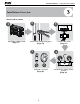
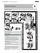
Installation Diagram
4
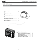
Installation Diagram
Installation
plate
Mounting screw
ST3.9
×25-C-H
Refrigerant
pipe
Remote
controller
holder
Clip anchor
(2)
•
This illustration is for demonstration
purposes only.
The actual shape of your air condtioner may
be slightly dierent.
•
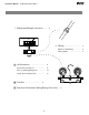
CAUTION
•
To prevent wall damage, use a stud nder to
locate studs.
A minimum pipe run of 3 metres is required
to minimise vibration & excessive noise.
Two of the A, B, and C air circulation pathways
must be free from obstructions at all times.
•
•
•
Copper lines must be independently insulated.
Safety Precautions
1
2
3
5
4
1
Installation plate
Clip anchor
(1)
Remote
controller
holder
5 4 3
2
The maximum
amount of the
connection cables is 5.
This section is for
reference only.
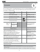
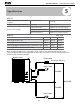
Air-break Switch
Drainage
Pipe
Air-break
Switch
Outdoor Unit
Power Cable
More than 5"
More than 5"
More
than 5"
More than 6"
More than 5"
24"
12"
80"
12"
24"
6"
5"
5"
24"
12"
12"
24"
80"
NOTE: The installation must be performed in
accordance with local and national standards.
The installation may be slightly different in
different areas.