HEAT CONTROLLER, INC. INSTALLATION INSTRUCTIONS Models: ODH, OHH, OUF, OLF, OLR Oil-Fired Furnaces A WARNING Improper installation, adjustment, alteration, service, or maintenance can cause injury or property damage. Refer to this manual. For assistance or additional information, consult a qualified installer or service agency. A WARNING Do not store combustible materials, including gasoline and other flammable vapors and liquids, near the furnace, vent pipe, or warm air ducts.
OIL FURNACE START-UP CHECKLIST (Complete this page and keep for future reference) See Combustion and Ventilation Alr on page 6. Customer Name Address City State Zip Code Furnace Model # Serial # Input Rate Nozzle Used New Construction Replacement Date of Installation Installation Data Start-Up Procedure Furnace Location: A. Close disconnect switch A. Basement Open Enclosed” B. Set thermostat to call for heat B. Enclosed" C. Bleed air from lines and pump; run for 20 seconds C.
INSTALLATION Read all instructions before starting work sa installation will conform to Underwriters’ Laboratories or Canadian Standards Association requirements. The fum ace must be level when placed on its foundation (up flow, counter flow, and basement models) or in ils suspended position (horizontal maddest. Using a carpenter's level, check the furnace in at least two directions. The weight must be distributed evenly before the duct work is attached.
than fire protection clearances, the accessibility clearances take precedence. Non-Suspended Horizontal Installation To support the furnace from below, set the furnace on non-combustible material suitable fo support the weight of the unit. Using a carpenter's level, check the fum ace in at least two directions. To make adjustments, use shims of non-combustible material. Seven inches minimum clear acne between the bottom of the flue pipe and combustible material is required.
Counter flow (Closet Installation) Combustible Floor Installation — fum ace for servicing the boomer and filter. A passage suitable for a large person shall be provided between the furnace and chimney for inspection or replacement of the flue connector when necessary. Figure 3 Figure 4 for more information on using a combustible floor base kit. Kits are also available for counter flow applications where a vestibule cover is needed for safety reasons. #46432A004 Counter flow Units St 1 —» pleb] ple.
Air Conditioning When an air conditioning unit is used in conjunction with the furnace, the evaporator coil must be installed in the discharge (supply) air. Do not install an evaporator coil in the return air; excessive condensation will occur within the fum ace. Venting Combustion air openings in the front of the furnace must be kept free of obstructions, Any obstruction will cause improper boomer operation and may result In a fire hazard or injury.
than specified in the Clearances section beginning on page 3. 7. The flue pipe may pass through a wall where provisions have been made for a thimble as specified in the Standards of the National Board of Fire Underwriters (see Figure 5). Wall Thimble ? 0 Combustible wa] [ Flue Pipe Figure 5 8. The flue pipe should slope upward toward the chimney on a horizontal run of at least 1/4” per foot and should be supported by something other than the furnace (see Figure 6 on this page and Figure 7 on page B). 9.
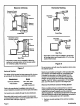
Masonry Chimney Barometric Control {in either location)® Front Flue Barometric Control {in either {location, Rear Flue * Barometric control may be installed in either the vertical or horizontal section of the flue pipe within 18" of the flue outlet of the furnace. Horizontal Venting Front Flue Barometric Control for Horizontal Venting Rear Flue * Barometric control must be installed in the horizon tal venting system and located within 48° of the flue outlet of the furnace.
2. Visually inspect the venting system for proper size and horizontal pitch and determine there Is no blockage or restriction, leakage, corrosion, or other deficiencies which could cause an unsafe condition. 3. Insofar as is practical, close all building doors and windows between the space in which the appliances remaining connected to the common venting system are located and other spaces in the building. Tum on clothes dryers and any appliance not connected to the common venting system.
an identical control as originally supplied on the equipment from the factory including “fan” and “limit” stops. The use of any other controls will void the warranty of the fum ace. Operation of this fum ace with greater than 130°F “Fan On" air temperature will also void the warranty of the furnace. Electrical Wiring All wiring must conform to the National Electrical Code, the Canadian Electrical Code, and any local codes. Connect the 115-volt, single phase service to the unit at the junction box.
locked out since its most recent complete heat cycle, the lockout time will be extended to 4 minutes, and the ignition will remain on for the entire heat cycle. Bleed the pump until all froth and bubbles are purged. The bleed port is located on the bottom of the fuel pump. To bleed, attach a clear plastic hose over the vent plug. Loosen the pug and catch the ofl inn empty container. Tighten the plug when all the air if purged. NOTE: Bleeding might not be necessary with a two-pipe system.
Beckett Oil Bummer Nozzle Adjustment Burner must be removed from furnace for this procedure. Gauge To adjust nozzle: 1. Loosen screw. 2. Slide entire nozzle/electrode assembly back and forth until nozzle just touches gauge. Figure 10 To check and adjust the nozzle depth: 1. Insert the small end of the “T” gauge into the end of the cone and measure from the flat of the and cone to the tip of the nozzle. The proper measurement should be 1.13".
Heat exchange clean out kit #ABRAHAM-3 is available from the manufacturer. Emergency Fuel Pump Replacement If replacement of the AZEA6520 fuel pump becomes necessary, replace it with another Beckett Clean Cut fuel pump. In an emergency situation whets the correct replacement parts are not available, an A2VA7 116 fusee pump could be used, This option can produce a smoky start-up and shutdown that could result in fouling of a heat exchange.
PO0OVZELBY # 1 beanbag gi gaffe LIVESTOCK Hed [BIUOZLIOH/MOJIBIUNOD BALI 19041] Wiesel contributory BLUE Ott EI ® © RED V1 3) HOT submission sox ¥i 7 AUX RELAY 4 GRIND.