INSTALLATION, OPERATION & MAINTENANCE MANUAL InverterFlex® Series Ceiling Cassette VFH12/18/24CA ATTENTION: Check for updates at www.heatcontroller.com Heat Controller • 1900 Wellworth Ave. • Jackson, MI 49203 • (517)787-2100 • www.heatcontroller.
VFH InverterFlex® - Ceiling Cassette Heat Controller TABLE OF CONTENTS Warnings and Cautions........................................................................................................ 1 Parts Identification................................................................................................................ 2 Installation Instructions......................................................................................................... 2 Service and Maintenance Clearances.......
Heat Controller VFH InverterFlex® - Ceiling Cassette • Read the follow SAFETY PRECAUTIONS carefully before installation. • Electrical work must be performed by a licensed electrician. • Incorrect installation due to ignoring the instruction will cause harm or damage. n The seriousness is classified by the following indications. ! WARNING! ! This symbol indicates the possibility of death or serious injury. CAUTION! This symbol indicates the possibility of injury or damage to property.
VFH InverterFlex® - Ceiling Cassette Parts Identification: Heat Controller Internal Condensate Pump Condensate Drain Hose Air Outlet Louvers Air Outlet Louver Air Filter Air Inlet Grille Remote Control (wireless) Wall Mounted Thermostat (Wired) Refrigerant Connecting Pipe (24K model only) Note: The connecting pipe is only provided with the 24K – see Line Set Installation section of the manual for information.
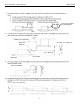
Heat Controller VFH InverterFlex® - Ceiling Cassette Service and Maintenance Clearances: Review the job site to ensure the area the unit is to be installed in will meet the required clearances. ATTENTION: Clearances should always be maintained for proper performance, maintenance and service. Ceiling Tile 10.2ft (260mm) >0.
VFH InverterFlex® - Ceiling Cassette Heat Controller 9. Installation is designed for new or existing ceilings. However, anchoring/mounting to wood, steel, and concrete must follow all local/national building codes. 10. Mounting hardware for suspension in ceiling must be acquired locally. M10 or 3/8” diameter threaded rods and nuts are the recommended to ensure a proper fit with the mounting flanges of the unit.
Heat Controller VFH InverterFlex® - Ceiling Cassette Mounting the Ceiling Cassette If needed, a cardboard template is included with each unit to act as an installation guide to ensure that the ceiling tiles are cut to the proper size and threaded rods are placed in the right locations to suspend the unit. ATTENTION: Before discarding the carton and/or packaging materials, locate the installation template: The 12/18K template is tucked around the top of the unit and is visible.
VFH InverterFlex® - Ceiling Cassette Heat Controller Line Set Installation ATTENTION: Refer to the Outdoor unit’s installation manual for all line set sizes and charging information. Create Opening for Refrigerant and Condensate lines 1. Determine hole position according the unit’s required clearances and which direction the lines will be routed from your unit. 2. Drill a 2.5”(65mm) hole angled downward (approx. 45°) toward the outdoors, if the line sets are being routed through a side wall.
Heat Controller VFH InverterFlex® - Ceiling Cassette Notes: 1. Do not over tighten or torque the connections. 2. Lubricating the connection with oil is recommended. Wrench Once the connections have been made, locate the (2) pieces of pipe insulation provided with your unit to insulate the union between the line set and unit connections: 1. Remove the adhesive backing and wrap the smaller diameter pipe insulation over the liquid connection. 2.
VFH InverterFlex® - Ceiling Cassette Heat Controller 3-5 ft. (1-1.5 mm) Incorrect do not allow any slack/sagging Pitch Within 11.8 in. (300 mm) Less than 11 in. (280 mm) 8.7 in. (220 mm) not to exceed 19.7 in. (500 mm) Drain Hose Adapter Hose Clamp not to exceed 3 in. (75 mm) Ceiling Tile min. 4.0 in. (100 mm) 8 at least 19.7 in.
Heat Controller VFH InverterFlex® - Ceiling Cassette 11. After all condensate piping is installed, ensure there are no leaks and that condensate will drain freely. 12. Test by slowly pour approximately 20oz (600ml) of water into the unit through the drain access location of the indoor unit. The square perforation in the foam of the housing is the knockout to access the condensate drain pan inside the unit. Notes: • The knockout is under the drain outlet on the 24K models as shown below.
VFH InverterFlex® - Ceiling Cassette Heat Controller Electrical Wiring WARNING: Wiring must conform to all local and national electric codes and be completed by an authorized installer. ATTENTION: Below are representative wiring diagrams for reference only. Always refer to the wiring diagram on the actual unit, as information is subject to change due to on-going product improvements.
Heat Controller VFH InverterFlex® - Ceiling Cassette 1. Heat Controller recommends using 600V THHN 14AWG/4 conductor unshielded stranded copper cable; however local and national codes for wire should always be followed based on your specific application. 2. The indoor unit’s terminal strip is located underneath the electrical box cover panel. 3. Loosen the screws to remove the cover. 4. Pull the conductor through the rubber grommet of the electric box. 5.
VFH InverterFlex® - Ceiling Cassette Heat Controller Wired Wall Thermostat Installation: The ceiling cassette comes with an optional wall mounted wired thermostat. ATTENTION: • Use of the wall mounted thermostat will disable both the unit’s control panel and the wireless remote. Alternatively, if the wall mounted thermostat is disconnected; both the unit’s control panel and wireless remote can be used to operate the unit.
Heat Controller VFH InverterFlex® - Ceiling Cassette 5. As the panel is being screwed in, ensure that it remains level on all sides. 6. The insulation material of the ceiling cassette panel will compress to create a tight seal. 7. Once installed, the inlet grille can be re-attached to the frame. The shipping screws on the tabs do not need to be re-installed.
VFH InverterFlex® - Ceiling Cassette Heat Controller 6. To remove the corner cover panels, simply reach inside the circular indentation and pull outward to toward the corner in the direction of the arrow shown below. • The cover is attached with magnets, so no heavy force is required to remove the corner covers. • Each corner cover is secured with a cable, so that it will not fall once it is removed. 7. With the cover removed from each corner, a leveling screw will be exposed.
Heat Controller VFH InverterFlex® - Ceiling Cassette WARNING: If a gap exists between the ceiling tiles and the ceiling cassette panel, condensate may leak. WARNING: If a gap exists between the ceiling tiles and the ceiling cassette panel, condensate may leak. Gap Panel Electrical Connections Panel Electrical Connections 1. Once the panel is installed, the connections can be made between the panel and the indoor unit. Onceare thetwo panel is installed, the connections 2. 1.
VFH InverterFlex® - Ceiling Cassette Heat Controller Care and Cleaning WARNING: Electrical Shock Risk - Always turn off the main power supply to the unit before performing any cleaning or maintenance! CAUTION: Do not use extremely hot water or harsh chemicals to clean, as they may deform or deteriorate the surface of the unit, filter or grille. 1. When the unit will not be used for an extended period of time, turn off the main power supply to the unit. 2.
Heat Controller VFH InverterFlex® - Ceiling Cassette Cleaning the Air Inlet Grille 1. The air inlet grille should be cleaned in addition to the air filter when it becomes dusty. 2. Using the same process above, open the air inlet grille and remove the filter. 3. The air inlet grille can be removed completely from the panel. 4. Vacuum the dust from the grille using a vacuum hose attachment with brush. If needed, the grille can be washed in lukewarm water and a mild detergent.
VFH InverterFlex® - Ceiling Cassette Heat Controller Troubleshooting WARNING: • • • All service and maintenance should be carried out by an authorized servicer. Do not try to service the unit yourself. If you notice a malfunction has occurred (such as abnormal noises, smoke or burning smells), turn off the power to the unit immediately and contact an authorized servicer. Always disconnect power before performing any service or maintenance.
Heat Controller VFH InverterFlex® - Ceiling Cassette Conditioned air might be escaping There is a time delay built into the unit to protect the compressor Unit will not run when turned on Improper temperature is set This is a normal occurrence when in cooling mode A mist is coming out of the outlet air louvers A click sound is heard once the unit begins to operate A hissing sound is heard continuously Strange noises are coming from the unit A hissing sound is heard when the unit starts up or just a
not run The unit will stand by for approximate one minute. As soon as power is on. The unit®blows VFH InverterFlex - Ceiling Cassette When the cooling operation starts. out mist The unit generates noise Heat Controller The hi-humidity air indoor is cooled quickly. The unit “clatters” as soon as it starts running. It is the sound generated during the initialization of the electronic expansion valve. The unit “swishes” during the cooling operation.
Refrigerant Recovery Mode Fo Quick Flashing Quick Flashing / Fo Fo Special Mode F3 / Flash 3 times / F3 F3 Outdoor Outdoor Mid-Coil Temp Sensor Error F4 / Flash 4 times / F4 F4 Outdoor Outdoor Discharge Air Temp Sensor Error F5 / Flash 5 times / F5 F5 Outdoor Oil Return for Cooling F7 / / / / / Special Mode Forced Defrosting H1 Quick Flashing / / H1 H1 Special Mode Oil Return for Heating or Defrosting H1 / / Flash once H1 Compressor Overheat Protection H
VFH InverterFlex® - Ceiling Cassette Heat Controller 7URXEOHVKRRWLQJ Low Voltage Protection PL Temp Drift Protection PE Drive Board Ambient Temp Sensor Error / / Flash 21 times PL PL Drive Error Flash 3 times Flash 3 times Flash 3 times PE PE Drive Error PF Flash 3 times Flash 3 times Flash 3 times PF PF Drive Error AC Current Protection PA Flash 5 times / / E5 E5 Drive Error Charging Circuit Error PU / / PU PU Drive Error AC Input Voltage Anomaly Flash 17 times PP
Heat Controller VFH InverterFlex® - Ceiling Cassette This page is left intentionally blank.
VFH InverterFlex® - Ceiling Cassette Heat Controller This page is left intentionally blank.
Heat Controller VFH InverterFlex® - Ceiling Cassette This page is left intentionally blank.
'XH WR RQJRLQJ SURGXFW LPSURYHPHQWV VSHFLILFDWLRQV DQG GLPHQVLRQV DUH VXEMHFW WR FKDQJH DQG FRUUHFWLRQ ZLWKRXW QRWLFH RU LQFXUULQJ REOLJDWLRQV 'HWHUPLQLQJ WKH DSSOLFDWLRQ DQG VXLWDELOLW\ IRU XVH RI DQ\ SURGXFW LV WKH UHVSRQVLELOLW\ RI WKH LQVWDOOHU $GGLWLRQDOO\ WKH LQVWDOOHU LV UHVSRQVLEOH IRU YHULI\LQJ GLPHQVLRQDO GDWD RQ WKH DFWXDO SURGXFW SULRU WR EHJLQQLQJ DQ\ LQVWDOODWLRQ SUHSDUDWLRQV ,QFHQWLYH DQG UHEDWH SURJUDPV KDYH SUHFLVH UHTXLUHPHQWV DV WR SURGXFW SHUIRUPDQFH DQG FHUWLILFDWLRQ $OO SUR