DIRECT-VENT FIREPLACE OWNER’S OPERATION AND INSTALLATION MANUAL ® REMOTE REQUIRES TWO 9-VOLT ALKALINE BATTERIES NOT INCLUDED CDV34(N/P) WARNING: If the information in this manual is not followed exactly, a fire or explosion may result causing property damage, personal injury, or loss of life. FOR YOUR SAFETY Do not store or use gasoline or other flammable vapors and liquids in the vicinity of this or any other appliance. FOR YOUR SAFETY WHAT TO DO IF YOU SMELL GAS • Do not try to light any appliance.
CDV34(N/P) DIRECT-VENT FIREPLACE (NATURAL/PROPANE/LP) SAFETY INFORMATION WARNINGS IMPORTANT: Read this owner’s manual carefully and completely before trying to assemble, operate, or service this fireplace. Improper use of this fireplace can cause serious injury or death from burns, fire, explosions, electrical shock, and carbon monoxide poisoning. 1. 2. 3. DANGER: Carbon monoxide poisoning may lead to death! This fireplace is a vented product.
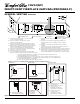
OWNER’S MANUAL PRODUCT IDENTIFICATION Top Louver Panel LOCAL CODES Install and use fireplace with care. Follow all local codes. In the absence to local codes, use the current National Fuel Gas Code ANS Z223.1, also known as NFPA 54* (USA) or the current CAN/CGA-B149[.1 or .2] Installation Codes (Canada). Vent Opening Nailing Flange *Available from: Standoff American National Standards Institute, Inc. 1430 Broadway New York, NY 10018 Glass Door Assembly National Fire Protection Association, Inc.
CDV34(N/P) DIRECT-VENT FIREPLACE (NATURAL/PROPANE/LP) PRE-INSTALLATION PREPARATION LOCATION AND SPACE REQUIREMENTS Determine the safest and most efficient location for your Comfort Glow direct-vent fireplace. Make sure that rafters and wall studs are not in the way of the venting system. Choose a location where the heat output is not affected by drafts, air conditioning ducts, windows or doors. Figure 2 shows some common locations. Read all venting information in this manual.
OWNER’S MANUAL PRE-INSTALLATION PREPARATION GENERAL VENTING These models are approved for use with Simpson Dura-Vent 6 5/8" direct-vent pipe components and terminations as well as both flex and rigid Comfort Glow vent components. Continued 13" 9 1/4" 41" 29" 12 5/8" 34 1/4" Nailing Tabs 34 3/4" 58" Figure 6 - Framing Clearances for Corner Installation 1 2 3 A 4 B Wall 5 C 6 D E 7 F LOCATION OF VENT TERMINATION G Top of Louver Opening Ref. Mantel Depth Ref.
CDV34(N/P) DIRECT-VENT FIREPLACE (NATURAL/PROPANE/LP) GENERAL VENTING Continued N N D H V L E B C Fixed Closed F B Openable Fixed Closed V Openable V I V G B V B B J X V G G M A V K X V A V TERMINATION CAP A = clearance above grade, veranda, porch, deck, or balcony [*12 inches (305mm) minimum] B = clearance to window or door that may be opened [12 inches (305mm) minimum] C = clearance to permanently closed window [minimum 12 inches (305mm) recommended to prevent condensation on win
OWNER’S MANUAL VENTING INSTALLATION WARNING: Read all instructions completely and thoroughly before attempting installation. Failure to do so could result in serious injury, property damage or loss of life. Operation of improperly installed and maintained venting system could result in serious injury, property damage or loss of life. WARNING: Seal all of the connections with high temperature silicone (600°F/316° C) every time a vent connection is made.
CDV34(N/P) DIRECT-VENT FIREPLACE (NATURAL/PROPANE/LP) Snorkel VENTING INSTALLATION Continued INSTALLATION FOR HORIZONTAL TERMINATION 1. Determine the route your horizontal venting will take. Note: The location of the horizontal vent termination on the exterior wall must meet all local and national building codes and must not be easily blocked or obstructed. 12" Minimum ,,,,, ,,,,, ,,,,, ,,,,, WARNING: Do not recess vent terminal into a wall or siding. 2.
OWNER’S MANUAL VENTING INSTALLATION 4. Continued 3. Attach vent pipe assembly to the fireplace. Set fireplace in front of it’s permanent location to insure minimum clearances. Mark the wall for a 10" square hole (for noncombustible material such as masonry block or concrete, a 7 1/2" diameter hole is acceptable). See Figure 12. The center of the hole should line up with the center-line of the horizontal rigid vent pipe.
CDV34(N/P) DIRECT-VENT FIREPLACE (NATURAL/PROPANE/LP) VENTING INSTALLATION Continued Horizontal Termination Configurations Figures 16 through 20 show different configurations for venting with horizontal termination. Each figure includes a chart with vertical minimum/maximum and horizontal maximum dimensions which must be met. All connections must be sealed with high temperature silicone sealant as specified in the second warning statement on page 7.
OWNER’S MANUAL VENTING INSTALLATION Continued Venting with Two 90° Elbows Vertical (V) Horizontal (H1) Horizontal (H1) + Horizontal (H2) 5' min. 6' min. 7' min. 8' min. 2' max. 4' max. 6' max. 8' min. 6' max. 12' max. 18' max. 20' max. 20' max. 8' max. 20' max. UP Figure 19 - Horizontal Termination Configuration for Rigid Venting Using Two 90° Elbows Venting with Two 90° Elbows Vertical (V) Horizontal (H1) + Horizontal (H2) 5' min. 6' min. 7' min. 8' min. 6' max. 12' max. 18' max. 20' max.
CDV34(N/P) DIRECT-VENT FIREPLACE (NATURAL/PROPANE/LP) VENTING INSTALLATION Flat Ceiling Installation 1. Continued INSTALLATION FOR VERTICAL TERMINATION 1. 2. Determine the route your vertical venting will take. If ceiling joists, roof rafters, or other framing will obstruct the venting system, consider an offset (see Figure 21) to avoid cutting loadbearing members.
OWNER’S MANUAL VENTING INSTALLATION Continued 3. 4. 5. Vertical Termination Configurations Figures 25 through 28 show four different configurations for vertical termination. All connections must be sealed with high temperature silicone sealant as specified in the second warning statement on page 7. Lower the support box through the hole in the roof until the bottom of the box extends at least 2" below the ceiling (see Figure 23). Align the support box vertically and horizontally using a level.
CDV34(N/P) DIRECT-VENT FIREPLACE (NATURAL/PROPANE/LP) VENTING INSTALLATION Continued Note: Restrictor must be installed in all vertical installations. CRVF Kit Shown Vertical Venting V = 30' max. Venting with Two 90° Elbows Vertical (V1) Horizontal (H) 5' min. 6' min. 7' min. 8' min. 6' max. 12' max. 18' max. 20' max. Figure 28 - Vertical Rigid Venting Configuration With No Horizontal Run Note: Vertical (V1) + Vertical (V2) = 20' max.
OWNER’S MANUAL VENTING INSTALLATION Continued Comfort Glow Rigid Venting (Cont.) Number Description Comfort Glow Flexible Venting CCVK CBFGFVK Basic Flex Ground Floor Vent Kit HIGH ALTITUDE INSTALLATION Your Comfort Glow direct-vent fireplace has been AGA tested and approved for elevations from 0-2000 feet and CGA certified for elevations from 0-4500 feet.
CDV34(N/P) DIRECT-VENT FIREPLACE (NATURAL/PROPANE/LP) FIREPLACE INSTALLATION NOTICE: This heater is intended for use as supplemental heat. Use this heater along with your primary heating system. Do not install this heater as your primary heat source. If you have a central heating system, you may run system’s circulating blower while using heater. This will help circulate the heat throughout the house. In the event of a power outage, you can use this heater as your primary heat source.
OWNER’S MANUAL FIREPLACE INSTALLATION 9. Continued 8. Plug in blower power cord. a. If your fireplace system is installed as a freestanding unit with an accessory mantel, determine whether the power cord will exit the left side or the right side of the firebox. Install one plastic bushing provided into the 1 1/2" hole in the outer casing through which the power cord will exit. Install the second plastic bushing provided into the floor support bracket if exiting through the right side (see Figure 33).
CDV34(N/P) DIRECT-VENT FIREPLACE (NATURAL/PROPANE/LP) FIREPLACE INSTALLATION Continued INSTALLING GAS PIPING TO FIREPLACE LOCATION WARNING: A qualified service person must connect fireplace to gas supply. Follow all local codes. CAUTION: For propane/LP units, never connect heater directly to the propane/LP supply. This heater requires an external regulator (not supplied). Install the external regulator between the heater and propane/LP supply. CAUTION: Use only new, black iron or steel pipe.
OWNER’S MANUAL FIREPLACE INSTALLATION Continued CONNECTING FIREPLACE TO GAS SUPPLY CHECKING GAS CONNECTIONS WARNING: Test all gas piping and connections for leaks after installing or servicing. Correct all leaks at once. Installation Items Needed • 5/16" hex socket wrench or nut-driver • sealant (resistant to propane/LP gas, not provided) 1. Open lower louver door panel by gently pulling forward. 2. Route flexible gas supply line through one of the access holes on side of fireplace. 3.
CDV34(N/P) DIRECT-VENT FIREPLACE (NATURAL/PROPANE/LP) FIREPLACE INSTALLATION Continued Test Pressures Equal To or Less Than 1/2 PSIG (3.5 kPa) 1. Close manual shutoff valve (see Figure 37). 2. Pressurize supply piping system by either opening propane/LP supply tank valve for propane/LP gas fireplace or opening main gas valve located on or near gas meter for natural gas fireplace, or using compressed air. 3.
OWNER’S MANUAL FIREPLACE INSTALLATION Continued INSTALLING OPTIONAL WIRELESS HAND-HELD REMOTE CONTROL NOTICE: Only use alkaline batteries (not included). Installing 9-Volt Alkaline Battery into Receiver 1. 2. 3. 4. 5. 6. Open bottom louver and locate the switch bracket on the left. Unscrew the switch bracket. Lean bracket forward so you are able to access the back of the remote receiver. Locate the battery clip mounted on the back of the receiver. Slide a 9-volt battery (not included) through the clip.
CDV34(N/P) DIRECT-VENT FIREPLACE (NATURAL/PROPANE/LP) FIREPLACE INSTALLATION Continued Attaching Magnetic Decorative Brass Strips This fireplace comes with a set of two magnetic decorative brass strips. Before attaching strips to fireplace, remove plastic film from brass pieces. After installing the door, attach these strips to the top and bottom of the glass door frame. INSTALLING OPTIONAL BRICK LINER CD8037 8. Loosely secure retainer brackets to grate.
OWNER’S MANUAL FIREPLACE INSTALLATION Continued INSTALLING LOGS, LAVA ROCK AND GLOWING EMBERS WARNING: Failure to position the parts in accordance with these diagrams or failure to use only parts specifically approved with this heater may result in property damage or personal injury. Each log is marked with a number. These numbers will help you identify the log when installing. It is very important to install these logs exactly as instructed. Do not modify logs. Only use logs supplied with fireplace. 1.
CDV34(N/P) DIRECT-VENT FIREPLACE (NATURAL/PROPANE/LP) OPERATING FIREPLACE WARNING: If you do not follow these instructions exactly, a fire or explosion may result causing property damage, personal injury or loss of life. A. This appliance has a pilot which must be lighted by hand. When lighting the pilot, follow these instructions exactly. B. BEFORE LIGHTING smell all around the appliance area for gas. Be sure to smell next to the floor because some gas is heavier than air and will settle on the floor.
OWNER’S MANUAL OPERATING FIREPLACE OPERATING OPTIONAL BLOWER ACCESSORY Continued HAND-HELD REMOTE OPERATION NOTICE: You must light the pilot before using the hand-held remote control unit. See Lighting Instructions, page 24. 2. After lighting, let pilot flame burn for about one minute. Turn control knob on the control valve to ON position. Turn flame adjustment knob anywhere between HI and LO. Turn the knob to the REMOTE setting.
CDV34(N/P) DIRECT-VENT FIREPLACE (NATURAL/PROPANE/LP) CLEANING AND MAINTENANCE WARNING: Turn off fireplace and let cool before cleaning. CAUTION: You must keep control areas, burners, and circulating air passageways of fireplace clean. Inspect these areas of fireplace before each use. Have fireplace inspected yearly by a qualified service person. Fireplace may need more frequent cleaning due to excessive lint from carpeting, bedding material, pet hair, etc.
OWNER’S MANUAL TROUBLESHOOTING WARNING: Turn off heater and let cool before servicing. Only a qualified service person should service and repair heater. Note: For additional help, visit DESA International’s Technical Service web site at www.desatech.com. CAUTION: Never use a wire, needle, or similar object to clean pilot. This can damage pilot unit. Note: All troubleshooting items are listed in order of operation.
CDV34(N/P) DIRECT-VENT FIREPLACE (NATURAL/PROPANE/LP) TROUBLESHOOTING Continued OBSERVED PROBLEM POSSIBLE CAUSE REMEDY Burner does not light after pilot is lit 1. Burner orifice clogged 1. Clean burner (see Cleaning and Maintenance, page 26) or replace burner orifice 2. Contact local propane/LP or natural gas company 3. Reconnect leads (see Wiring Diagram, page 30) 4. Replace thermopile 2. Inlet gas pressure is too low 3. Thermopile leads disconnected or improperly connected 4.
OWNER’S MANUAL TROUBLESHOOTING Continued WARNING: If you smell gas Shut off gas supply. Do not try to light any appliance. Do not touch any electrical switch; do not use any phone in your building. Immediately call your gas supplier from a neighbor’s phone. Follow the gas supplier’s instructions. • If you cannot reach your gas supplier, call the fire department. • • • • IMPORTANT: Operating fireplace where impurities in air exist may create odors.
CDV34(N/P) DIRECT-VENT FIREPLACE (NATURAL/PROPANE/LP) REPLACEMENT PARTS Note: Use only original replacement parts. This will protect your warranty coverage for parts replaced under warranty. WIRING DIAGRAM CAUTION: Label all wires prior to disconnection when servicing controls. Wiring errors can cause improper and dangerous operation. Verify proper operation after servicing. Variable Fan Switch PARTS UNDER WARRANTY Contact authorized retailers of this product.
OWNER’S MANUAL ACCESSORIES Purchase these fireplace accessories from your local retailer. If they can not supply these accessories, call DESA International’s Sales Department at 1-800-432-2382. for information. You can also write to the address listed on the back page of this manual. FIREPLACE SCREEN CDS34 For all models. This fireplace screen easily attaches to the front glass panel with included clips. RECEIVER AND HAND-HELD REMOTE CONTROL KIT CGHRC SERIES For all models.
CDV34(N/P) DIRECT-VENT FIREPLACE (NATURAL/PROPANE/LP) ILLUSTRATED PARTS BREAKDOWN CDV34(N/P)(A) 33 2 7 11 (Included in Hardware Pack) 44 37 6 43 31-1 31-2 25 42 26 27 29 1 31-3 38 31-4 6 20 18 32 34 6 4 19 16 24 36 30 28 21 22 35 14 17 28 46 15 9 5 8 23 13 12 5 45 39 5 32 40 10 32 3 7 41 32 105455
OWNER’S MANUAL PARTS LIST This list contains replaceable parts used in your fireplace. When ordering parts, follow the instructions listed under Replacement Parts on page 30 of this manual. DIRECT-VENT FIREPLACE CDV34(N/P)(A) KEY NO.
WARRANTY INFORMATION KEEP THIS WARRANTY Model Serial No. Date Purchased Always specify model and serial numbers when communicating with the factory. We reserve the right to amend these specifications at any time without notice. The only warranty applicable is our standard written warranty. We make no other warranty, expressed or implied.