Geothermal Applications APPLYING GEOTHERMAL COMFORT TO RESIDENTIAL CONSTRUCTION
Geothermal Applications Table of Contents 2 System Components ...........................................................................3 Flow Controller Selection ..............................................................15 The Geothermal Heat Pump .........................................................3 Flow Controller Performance Charts .....................................16 Packaged Water-to-Air Heat Pumps ..........................................4 Antifreeze Pressure Drop Tables .......
ClimateMaster Geothermal Heat Pump Systems System Components System Components Geothermal heat pumps have a number of names such as watersource heat pump, Geoexchange, ground loop heat pump, earthcoupled heat pump, ground source heat pump, etc. Technically, “Geothermal” is defined as, “energy from the internal heat of the earth.” This type of geothermal energy is called “high temperature geothermal.” Temperatures can exceed 300°F [150°C] in geothermal wells.
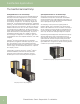
Geothermal Applications The Geothermal Heat Pump Packaged Water-to-Air Heat Pumps ClimateMaster has a number of choices for packaged geothermal heat pumps with airflow configurations for most any installation. Three families of two-stage products are available. Those are the Tranquility ® 30 Digital (TE), and Tranquility ® 30 (TT), and the Tranquility ® 22 Digital (TZ). The Tranquility ® Digital series include iGate™ communicating technology and vFlow™ variable flow technology.
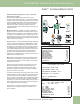
ClimateMaster Geothermal Heat Pump Systems iGate™ Communicating Controls iGate™ Information gateway to monitor, control and diagnose your system The Tranquility® Digital Series (TE, TZ, TEP, TES) is equipped with industry-first, iGate™ – Information Gateway – a 2-way communicating system that allows users to interact with their geothermal system in plain English AND delivers improved reliability and efficiency by precisely controlling smart variable speed components.
Geothermal Applications vFlow™ Internal Variable Water Flow Control vFlow™ Internal Variable Water Flow Industry-first, built-in vFlow™ replaces a traditionally inefficient, external component of the geothermal system (water circulation) with an ultra-high-efficient, variable speed, internal water flow system. This saves homeowners 70-80% on operating water circulator vs traditional single speed pump systems.
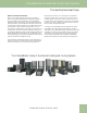
ClimateMaster Geothermal Heat Pump Systems The Geothermal Heat Pump Water-to-Water Heat Pumps Water-to-water heat pumps give the customer “the best of both worlds,” geothermal heating and cooling, plus the ability to enjoy the benefi ts of warm radiant floors. The ClimateMaster Tranquility ® TMW series water-to-water heat pumps provide hot and/or chilled water.
Geothermal Applications Heat Source/Heat Sink Heat Source/Heat Sink The heat source/heat sink for geothermal systems is determined based upon the specific application. Where water quality is good and a sufficient quantity of water is available, an open loop (well water) source/sink is a very cost effective solution. Otherwise, one of the three types of closed loop applications may be a better choice.
ClimateMaster Geothermal Heat Pump Systems Water Quality Standards Table 1: Water Quality Standards Water Quality Parameter HX Material Closed Recirculating Open Loop and Recirculating Well Scaling Potential - Primary Measurement Above the given limits, scaling is likely to occur. Scaling indexes should be calculated using the limits below pH/Calcium Hardness Method All - pH < 7.
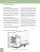
Geothermal Applications Heat Source/Heat Sink Open Loop Systems (continued) A closed, bladder-type expansion tank should be used to minimize mineral formation due to air exposure. The expansion tank should be sized to provide at least one minute continuous run time of the pump using its drawdown capacity rating to prevent pump short cycling. Discharge water from the unit is not contaminated in any manner and can be disposed of in various ways, depending on local building codes (e.g.
ClimateMaster Geothermal Heat Pump Systems Heat Source/Heat Sink Horizontal (Trenched or Bored) Loop Pond/Lake Loop Horizontal loops may be installed with a trencher, backhoe or horizontal boring machine. Excavation costs for horizontal loops are usually less than the costs for vertical loops, but significantly more land space is required. For rural installations, horizontal loops can be very cost effective. Pipe is typically buried around five feet [1.
Geothermal Applications Closed Loop Design/Installation Guidelines Closed Loop Basics Closed Loop Earth Coupled Heat Pump systems are commonly installed in one of three configurations: horizontal, vertical and pond loop. Each configuration provides the benefit of using the moderate temperatures of the earth as a heat source/heat sink. Piping configurations can be either series or parallel. Series piping configurations typically use 1-1/4 inch, 1-1/2 inch or 2 inch pipe.
ClimateMaster Geothermal Heat Pump Systems Closed Loop Design/Installation Guidelines In smaller loops of two tons [7 kW] or less, the reasons for using parallel loops as listed above may be less obvious. In these cases, series loops can have some additional advantages: • No header - fittings tend to be more expensive and require extra labor and skill to install. • Simple design - no confusing piping arrangement for easier installation by less experienced installers.
Geothermal Applications Closed Loop Design/Installation Guidelines Headers that utilize large diameter pipe feeding the last circuits should not be used. PE 1-1/4” IPS pipe requires 9.5 gpm [36 l/m] to attain 2 fps [0.6 m/s] and since increasing the flow through the last circuit would also require increasing the flow through the other circuits at an equal rate as well, we can estimate the flush flow requirements by multiplying the number of circuits by 9.5 gpm [36 l/m] for 1-1/4” IPS.
ClimateMaster Geothermal Heat Pump Systems Closed Loop Design/Installation Guidelines Inside Piping - Polyethylene pipe provides an excellent no leak piping material inside the building. Inside piping fittings and elbows should be limited to prevent excessive pressure drop. Hose kits employing 1” rubber hose should be limited in length to 10-15 feet [3 to 4.5 meters] per run to reduce pressure drop problems.
Geothermal Applications Closed Loop Design/Installation Guidelines Chart 1: Flow Controller Performance External Flow Controller Pump Curves 120 [360] 1-Grundfos 26-99 2-Grundfos 26-99 2-Grundfos 26-116 3-Grundfos 26-99 Head, ft [kPa] 100 [290] 80 [240] 60 [180] 40 [120] 20 [60] 0 GPM 0 1 2 3 4 5 6 7 8 9 10 11 12 13 14 15 16 17 18 19 20 21 22 23 24 25 26 27 28 29 30 0.06 0.13 0.19 0.25 0.32 0.38 0.44 0.50 0.57 0.63 0.69 0.76 0.82 0.88 0.95 1.01 1.07 1.14 1.20 1.26 1.32 1.38 1.45 1.51 1.
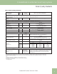
ClimateMaster Geothermal Heat Pump Systems Closed Loop Design/Installation Guidelines Table 3a: Polyethylene Pressure Drop per 100ft of Pipe Antifreeze (30°F [-1°C] EWT): 17% Methanol by volume solution - freeze protected to 15°F [-9.4°F] 3/4” IPS SDR11 1” IPS SDR11 1-1/4” IPS SCH40 1-1/2” IPS SCH40 PD (ft) Vel (ft/s) Re (ft) Vel (ft/s) Re PD (ft) Vel (ft/s) Re PD Vel (ft/s) Re PD Vel (ft/s) Re 1 0.35 0.55 1221 0.14 0.35 975 0.06 0.22 773 0.03 0.17 676 0.01 0.11 541 2 0.
Geothermal Applications Closed Loop Design/Installation Guidelines Table 3b: Polyethylene Pressure Drop per 100ft of Pipe Antifreeze (30°F [-1°C] EWT): 24% Propylene Glycol by volume solution - freeze protected to 15°F [-9.4°F] 18 3/4” IPS SDR11 Flow Rate PD (ft) Vel (ft/s) 1 0.59 2 1.18 3 1” IPS SDR11 Re (ft) Vel (ft/s) 0.55 716 0.24 1.10 1431 0.48 1.80 1.66 2147 4 4.45 2.21 5 6.96 2.76 6 9.48 7 12.31 8 15.
ClimateMaster Geothermal Heat Pump Systems Closed Loop Design/Installation Guidelines Table 3c: Polyethylene Pressure Drop per 100ft of Pipe Antifreeze (30°F [-1°C] EWT): 20% Ethanol by volume solution - freeze protected to 15°F [-9.4°F] 3/4” IPS SDR11 1” IPS SDR11 1-1/4” IPS SCH40 1-1/2” IPS SCH40 PD (ft) Vel (ft/s) Re (ft) Vel (ft/s) Re PD (ft) Vel (ft/s) Re PD Vel (ft/s) Re PD Vel (ft/s) Re 1 0.56 0.55 757 0.23 0.35 604 0.09 0.22 479 0.05 0.17 419 0.02 0.11 335 2 1.
Geothermal Applications Closed Loop Design/Installation Guidelines Table 3d: Polyethylene Pressure Drop per 100ft of Pipe Antifreeze (30°F [-1°C] EWT): 25% Ethylene by volume solution - freeze protected to 15°F [-9.4°F] 20 3/4” IPS SDR11 1” IPS SDR11 1-1/4” IPS SCH40 1-1/2” IPS SCH40 PD (ft) Vel (ft/s) Re (ft) Vel (ft/s) Re PD (ft) Vel (ft/s) Re PD Vel (ft/s) Re PD Vel (ft/s) Re 1 0.40 0.55 1048 0.16 0.35 837 0.06 0.22 664 0.04 0.17 580 0.02 0.11 464 2 0.81 1.
ClimateMaster Geothermal Heat Pump Systems Closed Loop Design/Installation Guidelines Table 3e: Polyethylene Pressure Drop per 100ft of Pipe No Antifreeze (50°F [10°C] EWT): Water 3/4" IPS SDR11 1" IPS SDR11 1 1/4" IPS SCH40 1 1/2" IPS SCH40 2" IPS SCH40 Flow Rate PD (ft) Vel (ft/s) Re PD (ft) Vel (ft/s) Re PD (ft) Vel (ft/s) Re PD (ft) Vel (ft/s) Re PD (ft) Vel (ft/s) Re 1 0.23 0.55 2,806 0.08 0.35 2,241 0.02 0.21 1,724 0.01 0.16 1,508 0.00 0.10 1,160 2 0.78 1.
Geothermal Applications Closed Loop Design/Installation Guidelines Table 3f: 1” Rubber Hose Pressure Drop per 100ft of Hose Methanol* Propylene Glycol* Ethanol* Water* Flow Rate PD (ft) Vel (ft/s) 1 0.12 0.35 895 0.14 0.35 507 0.13 0.35 807 0.12 0.35 923 2 0.42 0.70 1789 0.48 0.70 1013 0.43 0.70 1614 0.42 0.70 1847 3 0.85 1.06 2709 0.98 1.06 1534 0.88 1.06 2444 0.85 1.06 2796 4 1.41 1.41 3604 1.63 1.41 2041 1.45 1.41 3251 1.40 1.41 3720 5 2.09 1.
ClimateMaster Geothermal Heat Pump Systems Closed Loop Design/Installation Guidelines CAUTION! CAUTION! This manual is not intended for commercial loop design. Prior to installation, locate and mark all existing underground utilities, piping, etc. Install loops for new construction before sidewalks, patios, driveways and other construction has begun.
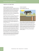
Geothermal Applications Closed Loop Design/Installation Guidelines Carefully backfill the boreholes with an IGSHPA approved Bentonite grout (typically 20% silica sand soilds by weight) from the bottom of the borehole to the surface. Follow IGSPHA specifications for backfilling unless local codes mandate otherwise. When all U-bends are installed, dig the header trench 4 to 6 feet [1.2 to 1.8 meters] deep and as close to the boreholes as possible.
ClimateMaster Geothermal Heat Pump Systems Closed Loop Design/Installation Guidelines Figure 10: Slab on Grade Entry Detail Figure 12: Pier and Beam (Craw Space) Detail Finished Grade 4-6' [1.2 - 1.8m Insulation Inside Protective Shield Loop Pipe Figure 13: Below Grade Entry Detail Figure 11: Retrofit Construction Detail Enter Building As Soon As Possible Insulation Inside Protective Shield Finished Grade 4-6' [1.2 - 1.
Geothermal Applications The Heating/Cooling Distribution System Ducted Forced Air System The most common type of heating and cooling distribution system is the ducted forced air system, which delivers warm or cool air to the living space. Water-to-air packaged units or split system heat pumps are typically connected to a central duct layout, which distributes conditioned air to the various zones. As in all forced air systems, properly designed and sealed ductwork is crucial to occupant comfort.
ClimateMaster Geothermal Heat Pump Systems The Heating/Cooling Distribution System and Equipment Sizing Figure 16: Typical Radiant Floor Header System The size of the buffer tank should be determined based upon the predominant use of the equipment (heating or cooling). For heating, buffer tanks should be sized at one U.S.
Geothermal Applications Equipment Sizing equipment sizing is still important, but some flexibility may be gained by including some of the latest technology. Regardless of location, local codes and/or electric utility program requirements always supersede any recommendations in this manual.
ClimateMaster Geothermal Heat Pump Systems Equipment Sizing Figure 19: Geo A Bin Report From GeoDesigner Software • Once the equipment is selected for sensible cooling and the proper size for heating has been determined, the latent cooling requirements should be considered. In the product catalog data, TC (Total Cooling capacity) and SC (Sensible Cooling capacity) are shown. Latent capacity equals TC minus SC.
Geothermal Applications Loop Sizing required in order to use the GeoDesigner software, since equipment and loop are determined based upon heat loss/heat gain. ClimateMaster heat pumps are designed for EWTs of 20°F [-7°C] to 120°F [49°C]. However, economical minimum and maximum loop temperatures should not be outside the range of 25°F [-4°C] and 105°F [41°C]. A good starting point for minimum EWT is 30 to 40°F [17 to 22°C] above the winter outdoor design temperature.
ClimateMaster Geothermal Heat Pump Systems Options Options ClimateMaster residential geothermal heat pumps have a number of options to customize the installation to the customer’s individual needs. a second preheat tank must be installed. If the electric water heater has only a single center element, the dual tank system is recommended to insure a usable entering water temperature for the HWG.
Geothermal Applications ClimaDry ® II ClimaDry ® II is a simple and easy to troubleshoot refrigerant circuit. No switching valves or hard to diagnose leaky check valves are utilized. No unusual refrigerant pressures occur during the reheat mode. The ClimaDry ® II refrigerant circuit is like every other ClimateMaster unit (without reheat), so everything the technician already knows applies to troubleshooting the ClimaDry ® II refrigeration circuit.
ClimateMaster Geothermal Heat Pump Systems ClimaDry ® II Figure 22: Example Size 030 Performance 3HUIRUPDQFH 'DWD 0RGHO /& 7& 6& 0%WXK %WXK OEV KU NJ KU &)0 1RPLQDO $LUIORZ 3HUIRUPDQFH FDSDFLWLHV VKRZQ LQ WKRXVDQGV RI %WXK
Geothermal Applications ClimaDry ® II Table 6: ClimaDry® II Operating Modes Input Mode Output Backup Reheat Elec Heat O G Y1 Y23 W H O G Y1 Y23 No Demand ON/OFF5 OFF OFF OFF OFF OFF ON/OFF5 OFF OFF OFF OFF OFF Fan Only ON/OFF5 ON OFF OFF OFF OFF ON/OFF5 ON OFF OFF OFF OFF Cooling 1st Stage ON ON ON OFF OFF OFF ON ON ON OFF OFF OFF Cooling 2nd Stage ON ON ON ON OFF OFF ON ON ON ON OFF OFF Cooling & Dehumidistat1 ON ON ON ON/OFF5 OFF ON ON
ClimateMaster Geothermal Heat Pump Systems ClimaDry ® II ClimaDry® II Application Considerations The reheat coil adds a small amount of resistance to the air stream. Consult the correction tables in this manual for details. Unlike most hot gas reheat options, the ClimaDry ® II option will operate over a wide range of EWTs. Special flow regulation (water regulating valve) is not required for low EWT conditions. Water-Source Heat Pumps with ClimaDry ® II should not be used as make-up air units.
Geothermal Applications ClimaDry ® II Table 7: Tranquility® 30 Blower Performance Data Residential Units Only Airflow in CFM with wet coil and clean air filter Model 026 038 049 064 072 Cooling Mode Dehumid Mode Heating Mode Fan AUX CFM Aux/ Emerg Mode 1060 475 4 1060 950 425 3 950 710 820 370 2 820 600 690 300 1 690 700 1120 1400 700 4 1400 980 630 1000 1250 630 3 1350 840 540 860 1080 540 2 1350 730 900 450 1 1350 870 1560 1850 870 4 1850 780
ClimateMaster Geothermal Heat Pump Systems ClimaDry ® II Table 8: Tranquility® 20 ECM Blower Performance Data Residential Units Only Airflow in CFM with wet coil and clean air filter Model 018 024 030 036 042 048 060 070 Max ESP (in. wg) 0.50 0.50 0.50 0.50 0.50 0.75 0.75 0.
Geothermal Applications ClimaDry ® II Table 9: Tranquility® 20 (TS) Series PSC Blower Performance Data (Without ClimaDry® II) Airflow (cfm) at External Static Pressure (in. wg) Model Fan Speed Rated Airflow Min CFM 0.00 0.05 0.10 0.15 0.20 0.25 0.30 0.35 0.40 0.45 0.50 0.60 0.
ClimateMaster Geothermal Heat Pump Systems ClimaDry ® II Table 10: Blower Performance Data - TS Units With ClimaDry® II (PSC Motor) Coil Face Velocity FPM TSH/V/D with Reheat ESP Loss TSH/V/D 018 In. of Water TSH/V/D 024, 030 In. of Water TSH/V/D 036 In. of Water TSH/V/D 042, 048 In. of Water TSH/V/D 060, 070 In. of Water 200 0.037 0.033 0.031 0.028 0.026 250 0.052 0.046 0.042 0.038 0.034 300 0.077 0.066 0.059 0.051 0.044 350 0.113 0.096 0.085 0.073 0.061 400 0.181 0.160 0.
Geothermal Applications Revision History 40 Date Page # Description 1 Feb. 13 All Added TE/TZ info., updated TT 27 to TT 30, various minor updates 10 June, 09 All Updated photos, tables, formatting, etc. 03 June, 09 30 Updated Figure 22: Example Size 030 Performance 03 June, 09 18 Updated Table 3d: Polyethylene Pressure Drop 05 June, 08 All Reformatted Document Size 30 April 08 All Minor Format Changes 01 Oct, 06 All First Published ClimateMaster: Smart. Responsible. Comfortable.