
System information


10
Geothermal Applications
ClimateMaster: Smart. Responsible. Comfortable.
Open Loop Systems (continued)
A closed, bladder-type expansion tank should be used to minimize
mineral formation due to air exposure. The expansion tank should
be sized to provide at least one minute continuous run time of the
pump using its drawdown capacity rating to prevent pump short
cycling. Discharge water from the unit is not contaminated in any
manner and can be disposed of in various ways, depending on
local building codes (e.g. recharge well, storm sewer, drain fi eld,
adjacent stream or pond, etc.). Most local codes forbid the use of
sanitary sewer for disposal. Consult your local building and zoning
department to assure compliance in your area.
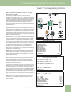
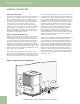
The placement of the water control valve is important for proper
operation. Figure 3 shows proper placement of the valve. Always
maintain water pressure in the heat exchanger by placing the
water control valve(s) on the discharge line to prevent mineral
precipitation during the off-cycle. Pilot operated slow closing valves
are recommended to reduce water hammer. Insure that the total
‘VA’ draw of the valve can be supplied by the unit transformer.
For instance, a slow closing valve can draw up to 35VA. This can
overload smaller 40 or 50 VA transformers depending on the
other controls in the circuit. A typical pilot operated solenoid valve
draws approximately 15VA.
Flow regulation for open loop systems can be accomplished by two
methods. One method of fl ow regulation involves simply adjusting
the ball valve or water control valve on the discharge line. Measure
the pressure drop through the unit heat exchanger, and determine
fl ow rate from tables in the installation manual of the specifi c unit.
Since the pressure is constantly varying, two pressure gauges may
be needed. Adjust the valve until the desired fl ow of 1.5 to 2 gpm
per ton [2.0 to 2.6 l/m per kW] is achieved. A second method of
fl ow control requires a fl ow control device mounted on the outlet
of the water control valve. The device is typically a brass fi tting
with an orifi ce of rubber or plastic material that is designed to
allow a specifi ed fl ow rate. On occasion, fl ow control devices may
produce velocity noise that can be reduced by applying some back
pressure from the ball valve located on the discharge line. Slightly
closing the valve will spread the pressure drop over both devices,
lessening the velocity noise. NOTE: When EWT is below 50°F
[10°C], 2 gpm per ton [2.6 l/m per kW] is required.
Closed Loop Systems
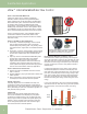
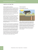
Vertical (Drilled) Closed Loop
Vertical or drilled closed loop systems take up the least amount
of land or yard space. Since the heat exchange takes place along
the vertical drilled (bore) hole walls, only a small diameter hole
(typically 4” [10 cm]) is required for each ton [3.5 kW] of heat
pump capacity. Minimal spacing is required between bore holes,
typically 15 feet [4.6 meters] for residential applications. Depending
upon drilling costs, vertical loops may be more expensive than
horizontal or pond/lake loops, but their compact layout makes a
geothermal closed loop application possible for almost any home
that has a small yard, driveway or sidewalk. Loops can even be
installed underneath the foundation. Closed loop design and
installation guidelines (later in this section) provide details on
vertical loop designs.
Heat Source/Heat Sink