
System information


ClimateMaster Geothermal Heat Pump Systems
5
Residential Products Technical Guide
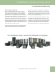
iGate™ Information gateway to monitor, control and
diagnose your system
The Tranquility
®
Digital Series (TE, TZ, TEP, TES) is
equipped with industry-fi rst, iGate™ – Information Gateway –
a 2-way communicating system that allows users to interact
with their geothermal system in plain English AND delivers
improved reliability and effi ciency by precisely controlling
smart variable speed components. iGate™ makes the
Tranquility Digital series the easiest geothermal products to
install and service.
Monitor/Confi gure – Installers can confi gure Tranquility
®
Digital units from the thermostat, including: Air fl ow, loop ∆T,
water-fl ow option confi guration, unit confi guration, accessory
confi guration, and demand reduction (optional, to limit unit
operation during peak times). Users can look up the current
system status: temperature sensor readings and operational
status of the blower and pump.
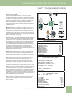
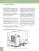
Precise Control - The new DXM2 board enables intelligent,
2-way communication between the DXM2 board and smart
components like the communicating thermostat, fan motor,
and water pump. The DXM2 control can also directly control
the modulating valve and accepts various feedback/input.
The Intelligent DXM2 board uses information received from
the smart components and sensors to precisely control
operation of the variable-speed fan and variable-speed
water pump (or modulating valve) to deliver higher effi ciency,
reliability and increased comfort.
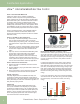
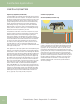
Diagnostics – iGate™ takes diagnosing geothermal units
to the next level of simplicity, by providing a dashboard of
system and fault information, in plain English, on the iGate
thermostat/ service tool.
iGate™ Service Warning warns the homeowner of a fault
and displays dealer information (if programmed), fault
descriptions, possible causes and current system status
(temperature readings, fan RPM and water fl ow status) to
provide to a dealer on the phone.
In iGate™ Service Mode, the service personnel can access
fault descriptions, possible causes and most importantly, the
conditions (temp, fl ow, i/o conditions, confi guration) at the
time of the fault and at the time of the call. Manual Operation
mode allows the service personnel to manually command
operation for any of the thermostat outputs, blower speed, as
well as pump speed or valve position from the thermostat, to
help troubleshoot specifi c components.
With the iGate™ communicating system, consumers and
contractors have a gateway to system information never
before available.
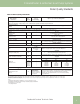
AIRFLOW SELECTION
CFM
HEAT STAGE 1 600
HEAT STAGE 2 750
AUXILIARY HEAT 850
EMERGENCY HEAT 850
COOL STAGE 1 525
COOL STAGE 2 700
COOL DEHUMID 1 425
COOL DEHUMID 2 550
CONTINUOUS FAN 350
HEAT OFF DELAY 60
COOL OFF DELAY 30
PREVIOUS NEXT
POSSIBLE FAULT CAUSES
LOW WATER COIL TEMP
LOW WATER TEMP - HTG
LOW WATER FLOW - HTG
LOW REFRIG CHARGE - HTG
INCORRECT LT1 SETTING
BAD LT1 THERMISTOR
PREVIOUS
FAULT TEMPERATURE CONDITIONS
LT1 LOW WATER TEMP
HEAT 1 11:11 AM 11/14
LT1 TEMP 28.1
LT2 TEMP 97.3
HOT WATER EWT 121.5
COMP DISCHARGE 157.7
LEAVING AIR 92.7
LEAVING WATER 34.9
ENTERING WATER 42.1
CONTROL VOLTAGE 26.4
PREVIOUS
iGate™ Communicating Controls
iGate™ System