
Use and Care Manual


3
3
www.comfortzoneproducts.com
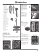
PARTS IDENTIFICATION
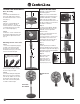
ASSEMBLY INSTRUCTIONS
Fan Head Assembly:
Step 1:
Set the back grille on the motor shaft. Make sure that the internal
molded arrow (Fig. 1a) points up and the 4 clips t properly. Push
rmly in order to t them tightly (Fig. 1b). Make sure they are
secure.
Step 2:
Using a Philips-head
screwdriver, screw the
3x8mm screew with
washer top (included
in the parts kit) into the
cylinder-shaped housing
at the top of the grille
(Fig. 2).
Step 3:
Set the fan blades on
the shaft of motor body
and screw the blades
nut toward the word
"THIGHTEN" as the
arrows show (Fig. 3).
Step 4:
Place the front and back
grilles together by aligning
the 12 clips, pushing rmly
until a "click" sound is
heard (Fig. 4a, 4b).
Step 5:
• Take the M3mm nut (from
the parts kit) and place it on
the hex socket at the bottom
of the rear grille (Fig. 5a).
• Next, take the M3x20mm
screw (from the parts kit)
and place it on the socket at
the bottom of the front grille
(Fig. 5b.
• Secure the screw to the
nut to ensure the rm grip of
both grilles using a Philips-
head screwdriver.
Fig. 1a Fig. 1b
Fig. 2
Fig. 4b
Fig. 4b
Fig. 3
Clip
Nut Screw
Fig. 5a
Fig. 5b
1
2
6
8
7
3
9
10
11
13
14
12
16
17
18
4
5
5
20
3
15
19
1. Front grille
2. Rear grille
3. Grilles’ clips
4. ST 3x8mm Screw
with washer top:
(secures rear grille
to motor cover)
5. M3x20 Screw
and M3 Nut
(secure grilles'
interlock)
6. Fan blades
7. Blades nut
8. Motor shaft
9. Motor body
10. Oscillation switch
11. Operation/Speed
control panel
12. Fan-to-pole xing
knob
13. Telescopic pole
14. Height xing ring
15. Telescopic tube
16. Fan base
17. Counterweight
18. Washer
19. L- screw
20. Wall fan support
bracket