User Manual for the COMM-TEC EIB Gateway CTG-KNX/IP (v1.0.
Table of contents 1 2 3 4 5 6 7 8 Introduction.....................................................................................................................................3 1.1 Aims?..........................................................................................................................................3 1.2 Role of the EIB installer ..............................................................................................................3 1.
1 Introduction 1.1 Aims The software module is being used to connect AVIT and AMX control systems to the "European Installation Bus" EIB ("Instabus"). It provides an easy to use interface for developers to comfortably access the bus. 1.2 Role of the EIB installer It can not be expressed strongly enough: when connecting to an EIB system, solid knowledge of the EIB and close contact to experienced EIB installers is strongly recommended.
NetLinx Master NetLinx Program Virtual Device NetLinx Module Figure 1 – Process of Communication -4- EIB Gateway
1.4 EIB details when using the Gateway CTGKNX/IP CTGKNX/IP In principle, the EIB gateway CTG-KNX/IP is a normal EIB device, and can therefore be connected at any location to the EI bus. Unlike simple actuators or sensors it can be responsible for a large amount (up to 3000) of group addresses – a normal dimmer for example, just reacts to four addresses. So one must be very careful to ensure that the gateway has a real chance to react to all bus telegrams of interest.
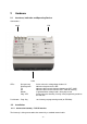
2 Hardware 2.1 Interfaces, Indication and Operating Devices Connections : 230 V EIB RJ45 LEDs : Busspannung Bustelegramm TX RX Betrieb Prog.-LED Push-button : Prog.-Key 2.2 2.2.
3 Programming 3.1 Integrating the Module At first, the program needs to get the information, what the Gateway’s IP-Address is. This can be done by the Online_Event of the virtual Devices: DATA_EVENT[vdvEIB] { ONLINE : { SEND_COMMAND vdvEIB,'IP=172.16.100.123' } } (also see Appendix) The Port for the Gateway has been set to 10002, which can not be edited. The IP-Address will be set by the included gateway software. On delivery, the Ethernet Address of the Gateway is set to 192.168.1.106.
on an „AMX number between 1 and 3000. Communication with the actuators concerned is only made via this number. This tabel is integrated with the following source code line: #INCLUDE 'EIB_Table.axi' An example for such a file and a sample program is contained in Appendix A. In addition, the file EIB_Tools.AXI should be integrated to have easy access to commonly used functions (see Appendix B). #INCLUDE 'EIB_Tools.axi' 3.
3.3 The NetLinx module interface 3.3.1 Commands for module Commands to the module always take place per SEND_COMMAND to the virtual device.
Command Description EIS5? Inquiry EIS5 value Converts the 2Byte raw data into ASCII string with floating point Note: Only valid for actuators type 2Byte - 1_3000 = AMX number of actuator GET= GET? Example: SEND_COMMAND vdvEIB,’EIS5:12’ Inquiry of actuator value stored in the module Note: Creates no telegram on EIB (for synchronization of master-to-master connection only use POLL command) - 1 … 3000 = AMX number of actuator POLL= POLL? Example: SEND_COMMAND vdvEIB, ’GE
3.3.2 Feedback from module The feedback is always in STRING format. The module can generate the following feedback: String Description DATE=: Feedback of date Note: Is transmitted as ADDITIONAL feedback, if in actuator the DATE flag is set. - 1 … 3000 = AMX number of actuator - Date string in format MM/DD/YY (AMX display) EIS5=: Example: DATE=17:08/14/06 Feedback of a value in ASCII floating point display. The actuator value to be coded according to EIS5.
Command Description ADR_ Definition of output format of EIB group address (Main/medium/sub group OR main group/sub group) - 2/3 DEL_ Example: SEND_COMMAND vdvEIB,’ADR 3’ Delete actuator from table - 1 … 3000 = AMX number of actuator HELP /? LIST LIST_ Example: SEND_COMMAND vdvEIB,’DEL 3’ Output of available monitor commands Example: SEND_COMMAND vdvEIB,’HELP’ List all entered actuators with AMX number, EIB group address, current value, set flags (if applicable) and re
Command Description LIST_- List actuators in the range of to (AMX numbers) with EIB group address, current value, set flags (if applicable) and resulting additional acknowledgement values - 1 … 3000 = AMX number of actuator (start) - 1 … 3000 = AMX number of actuator (end) LIST_FLAGS LIST_LOAD_[] LIST_POLL LIST_SAVE_[] LIST_SUM LIST_WATCH LIST_GAPS Example: SEND_COMMAND vdvEIB,’LIST 17-24’ List ALL actuators with assigned flags in table with EIB
3.3.4 Channels and levels All addresses are available as channels. The current value is displayed on the corresponding channels of the virtual device. For value report “0” the channel is OFF, for all other values ON. Channel 1 … 3000 3001 3002 Description Display of values (irrespective of EIB type) Gateway was detected, module ready for ADD = commands Gateway and module function correct The first 200 addresses (actuators in EIB table) are available as levels.
5 Appendix A – Sample program 5.1 Notes EIB table All actuators to be switched/set/controlled are to be introduced to the gateway. This is achieved with a table structure. If this table is generated with a help file (i.e. ‘EIB_Table.AXI’) it must only be observed, that all entries are edited, meaning the last Switch_Case command (default:) is really edited last. There is to be no gap in the counter. For the entries itself the order is irrelevant.
5.2.1 Example 1 – Structure of EIB table with functions from EIB_Tools.
5.2.
5.2.3 Example 3 – Enter addresses from file The address table can be read and generated from file on CF card. The reading of the file can for instance be started in the ONLINE section of the interface. (Description see chapter “Monitor mode”) Note: Comments at the end of a line must be separated by at least one space und are initiated – corresponding with programming – with “//”. Only one command per line is permitted. Leading spaces are ignored.
5.2.
6 Appendix B – EIB_Tools.AXI We recommend not to use the send commands directly, but always utilize the functions of this include file. The compiler has the opportunity to avoid typing errors already during compiling. Additional typing is avoided. This file also provides absolute terms for relative dimming: The following functions are available in file EIB_Tools.
7 Appendix C – Comparison with previous version The general operation of hardware and software has not changed. A filter table has still to be generated and loaded into the gateway. Via this filter the incoming and outgoing telegrams are filtered. The control of actuators or acknowledgements from sensors takes place by setting of values, which are assigned to certain addresses. - in order to limit the busload created by AMX on the EIB, - approx.
8 Appendix D – What to do if it does not work? The following table provides tips for error definition, in case it does not work. This serves a quick error analysis ON SITE. We recommend activating debugging mode during diagnostics to display additional error messages. This is activated with monitor command “DEBUGON”.