Item # 1000000000 Model # 50242161 Use and Care Guide 2 FT. Linear High Bay Questions, problems, missing parts? Before returning to the store, call Commercial Electric Customer Service 8 a.m. – 7 p.m., EST, Monday - Friday 9 a.m. - 6 p.m., EST, Saturday 1-877-527-0313 HOMEDEPOT.COM THANK YOU We appreciate the trust and confidence you have placed in Commercial Electric through the purchase of this LED light. We strive to continually create quality products designed to enhance your home.
Table of Contents Table of Contents. . . . . . . . . . . . . . . . . . . . . . . . . . . . . . . . . . . . 2 Safety Information. . . . . . . . . . . . . . . . . . . . . . . . . . . . . . . . . . . 2 Warranty. . . . . . . . . . . . . . . . . . . . . . . . . . . . . . . . . . . . . . . . . . . 2 Pre-Installation. . . . . . . . . . . . . . . . . . . . . . . . . . . . . . . . . . . . . . 3 Planning Installation . . . . . . . . . . . . . . . . . . . . . . . . . . . . . . . . 3 Tools and Hardware Required. . . .
Pre-Installation PLANNING INSTALLATION Before beginning assembly, installation, or operation of the product, make sure all parts are present. Compare the parts with the package contents list and hardware included list. If any part is missing or damaged, do not attempt to assemble, install, or operate the product. Contact the customer service team for replacement parts. NOTE: Keep your receipt and these instructions for proof of purchase.
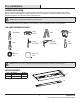
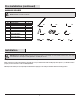
Pre-Installation (continued) HARDWARE INCLUDED NOTE: Hardware not shown to actual size. Part AA BB CC DD EE FF GG HH II JJ Description Mounting Chain S-Hook Wire Connector V-Clip Mounting Bracket Cover Plate Mini Conduit Adapter for Downrod Mounting Type 1/2 Conduit Adapter for Downrod Mounting Long Screw Short Screw Quantity 2 2 3 2 1 2 1 AA BB DD CC EE FF 1 2 10 GG HH II JJ Installation WARNING: RISK OF ELECTRIC SHOCK. Ensure the electricity to the wires you are working on is shut off.
Suspension Mounting 1 Making marks on the ceiling 2 Mounting to a drywall ceiling 24.6 in. □□ Mark two spots on the ceiling 24.6 in. apart for suspension mounting before the installation. 3 □ Drill two holes large enough to clear the closed flaps of the butterfly nut on a toggle bolt (not included). Mounting to a wood ceiling □□ Drill two 1/16 in. diameter holes in the ceiling to accommodate hook screws (not included).
Suspension Mounting (continued) 5 Preparing the fixture body for mounting □□ Attach the V-clip (DD) to the hanging holes on the fixture body (A). □□ Attach the hook on one end of the mounting chain (AA) to the center of the V-clip (DD) and close the hook with pliers to secure it. □□ Repeat these steps with the second V-clip (DD) and mounting chain (AA) on the opposite end of the fixture body (A).
Suspension Mounting (continued) 7 Making the electrical connections □□ Feed the electrical wires from the fixture body (A). □□ Connect the hot and neutral (black and white) wires from the fixture body (A) to the same color wires from the electrical box. □□ Connect the ground (green) wire from the fixture body (A) to the ground wire from the power supply cover plate and the ground wire from the electrical box. □□ Cover the wire connections using the wire connectors (CC).
Surface Mounting (continued) 2 Attach the fixture to the mounting surface □□ Remove the screw that attaches the power supply cover plate to the fixture body (A). □□ Feed the wiring from the electrical box out through the mounting bracket (EE). □□ Align the slots on the fixture body (A) with the mounting bracket (EE).
Downrod Mounting 1 Install the mounting bracket □□ Remove the screw that attaches the power supply cover plate to the fixture body (A). □□ Push the mounting bracket (EE) onto the downrod (not included) and secure the mounting bracket (EE) to the downrod (not included) using a nut (not included). Downrod Power supply cover plate EE Nut NOTE: Please use type 1/2 or type 3/4 standard downrod for downrod mounting.
Downrod Mounting (continued) 2 Attach the fixture to the mounting surface □□ Feed the wiring out through the downrod from the electrical box, and into the fixture body (A). □□ Refer to the installation steps for surface mounting. Align the slots on the fixture body (A) with the mounting bracket (EE).
Adjusting the Motion Sensor Settings Detection distance Max. 26.2 ft. Detection angle 30°-150° Operating temperature -40℃~ +60℃ Mounting height 29.5 ft.-52.5 ft. (ceiling mounted) Hold-time 5 min/10 min/30 min/+∞ Stand-by period 5 min/10 min/30 min/+∞ Stand-by dimming level 30% Hold time 5min 10min 30min Ceiling Mounted +∞ 29.5 ft - 52.5 ft 5min 10min 30min Detection distance +∞ Max. 26.2 ft. Standby time Hold time Light turns on at 100% full brightness when movement is detected.
Light Distribution 1300 2600 3900 5200 6500 UNIT: cd C 0 / 180, 103.4 C 30 / 210, 103.1 C 60 / 240, 102.3 AVERAGE BEAM ANGLE (50%) : 102.7DEG 12 C 90 / 270, 101.
Care and Cleaning CAUTION: Before attempting to clean the fixture, disconnect the power to the fixture by turning the breaker off or removing the fuse from the fuse box. □□ Clean the fixture with a soft, dry cloth. □□ Do not use cleaners with chemicals, solvents, or harsh abrasives. □□ Do not use liquid cleaner on the LEDs, LED driver, or wiring inside the light fixture. Troubleshooting WARNING: Before doing any work on the fixture, disconnect power to the light fixture.
Questions, problems, missing parts? Before returning to the store, call Commercial Electric Customer Service 8 a.m. – 7 p.m., EST, Monday - Friday 9 a.m. - 6 p.m., EST, Saturday 1-877-527-0313 HomeDepot.COM Retain this manual for future use.
Artículo # 1000000000 Modelo # 50242161 GUÍA DE USO Y CUIDADO LÁMPARA LINEAL DE 2 PIEDS PARA TECHOS ALTOS ¿Preguntas, problemas, piezas faltantes? Antes de devolver el producto a la tienda, llame al Centro de Atención al Cliente de Commercial Electric en el horario de 8 a.m. – 7 p.m., Hora del Este de EE.UU., de lunes a viernes. 9 a.m. – 6 p.m., Hora del Este de EE.UU., sábados. 1-877-527-0313 HomeDepot.
Contenido Contenido. . . . . . . . . . . . . . . . . . . . . . . . . . . . . . . . . . . . . . . . . 16 Informacíon sobre seguridad. . . . . . . . . . . . . . . . . . . . . . . . . . 16 Garantía. . . . . . . . . . . . . . . . . . . . . . . . . . . . . . . . . . . . . . . . . . 16 Previo a la Instalación. . . . . . . . . . . . . . . . . . . . . . . . . . . . . . . 17 Planning Installation . . . . . . . . . . . . . . . . . . . . . . . . . . . . . . . 17 Herramientas y materiales necesarias . . . . . . . . . .
Previo a la Instalación PLANIFICACÍON DE LA Instalación Antes de comenzar el armado, instalación u operación del producto, asegúrese de que tiene todas las piezas. Compare las piezas con la lista de contenido y lista de materiales. Si alguna de las piezas faltara o estuviera dañada, no proceda a armar, instalar u operar el producto. Comuníquese con el servicio al cliente para consultar por las piezas de reemplazo. NOTA: Guarde el recibo de compra y estas instrucciones como prueba de compra.
Previo a la Instalación (continuación) MATERIALES INCLUIDOS NOTA: Los materiales no se ilustran en tamaño real. Pieza AA BB CC DD EE FF GG HH II JJ Descripción Cadena Gancho S Conector de cable Clip en V Soporte de montaje Cubierta de caja Mini adaptador de conducto para montaje con barra Adaptador de conducto tip 1/2 para montaje con barra Tornillo largo Tornillo corto Cantidad 2 2 3 2 1 2 1 AA BB DD CC EE FF 1 2 10 GG HH II JJ Instalación ADVERTENCIA: RIESGO DE DESCARGA ELÉCTRICA.
Montaje en suspensión 1 Hacer marcas en el techo 2 Instalación sobre panel de yeso 24.6 pulg. □□ Antes de la instalación, marque dos puntos en el techo con una separación de 24.6 pulgadas para el montaje en suspensión. 3 □□ Taladre dos agujeros lo suficientemente grandes como para despejar las aletas cerradas de la tuerca mariposa en un perno de palanca (no incluido). Instalación sobre madera □□ Perfore dos agujeros de 1/16 pulg.
Montaje en suspensión (continuación) 5 Preparar la caja de la lámpara para el montaje □□ Fije el clip en V (DD) a los orificios de suspensión en la caja de la lámpara (A). □□ Fije el gancho en un extremo de la cadena de montaje (AA) al centro del clip en V (DD) y cierre el gancho con alicates para asegurarlo. □□ Repita estos pasos con el segundo clip en V (DD) y la cadena de montaje (AA) en el extremo opuesto de la caja de la lámpara (A).
Montaje en suspensión (continuación) 7 Hacer las conexiones eléctricas □□ Pase los cables desde la lámpara (A). □□ Conecte los cables principal y neutro (negro y blanco) de la caja de la lámpara (A) a los cables del mismo color de la caja eléctrica. Cubierta de la fuente de alimentación CC A □□ Conecte el cable de tierra (verde) de la caja de la lámpara (A) al cable de tierra de la cubierta de la fuente de alimentación y al cable de tierra de la caja eléctrica.
Instalación en superficie (continuación) 2 Fijar la lámpara a la superficie de montaje □□ Retire el tornillo que une la cubierta de la fuente de alimentación a la caja de la lámpara (A). □□ Pase los cables desde la caja eléctrica a través del soporte de montaje (EE). □□ Alinee las ranuras de la caja de la lámpara (A) con el soporte de montaje (EE).
Instalación con barra 1 Instalar el soporte de montaje □□ Retire el tornillo que une la cubierta de la fuente de alimentación a la caja de la lámpara (A). □□ Empuje el soporte de montaje (EE) sobre la barra (no incluida) y asegure el soporte de montaje (EE) a la barra (no incluida) con una tuerca (no incluida). Barra rigida Cubierta de la fuente de alimentación EE NOTA: Por el montaje con barra, utilice una barra estándar de tipo 1/2 o tipo 3/4.
Instalación con barra (continuación) 2 Fijar la lámpara a la superficie de montaje □□ Pase los cables a través de la barra desde la caja eléctrica y dentro de la caja de la lámpara (A). □□ Consulte los pasos de instalación para el montaje en superficie. Alinee las ranuras de la caja de la lámpara (A) con el soporte de montaje (EE).
Ajuste del sensor de movimiento Configuraciones Distancia de detección Max. de 26.2 pies Ángulo de detección 30°-150° Temperatura de funcionamiento -40℃~ +60℃ Altura de montaje 29.5 a 52.2 pies (montado en el techo) Tiempo de espera 5 min/10 min/30 min/+∞ Período de espera 5 min/10 min/30 min/+∞ Nivel de atenuación en espera 30% Tiempo de espera 5min 10min 30min Montado en el techo +∞ 29.5 a 52.5 pies 5min 10min 30min Distancia de detección +∞ Max. de 26.
Distribución de la luz 1300 2600 3900 5200 6500 UNIT: cd C 0 / 180, 103.4 C 30 / 210, 103.1 C 60 / 240, 102.3 ÁNGULO PROMEDIO DE HAZ (50%) : 102.7DEG 26 C 90 / 270, 101.
Cuidado y limpieza PRECAUCIÓN: Antes de limpiar la lámpara, desconecte el suministro eléctrico hacia ésta apagando el cortacircuitos o extrayendo el fusible de la caja de fusibles. □□ Limpie la lámpara con un paño suave y seco. □□ No utilice limpiadores con productos químicos, solventes o abrasivos. □□ No use limpiador líquido en las bombillas LED, en la unidad LED ni en los cables que están dentro de la lámpara.
¿Preguntas, problemas, piezas faltantes? Antes de devolver el producto a la tienda, llame al Centro de Atención al Cliente de Commercial Electric en el horario de 8 a.m. – 7 p.m., Hora del Este de EE.UU., de lunes a viernes. 9 a.m. – 6 p.m., Hora del Este de EE.UU., sábados. 1-877-527-0313 HomeDepot.COM Conserve este manual para uso futuro.