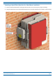
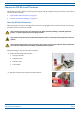
Installing CAP Ms Attaching a Hybrid Fiber Splice Box for a Dual Mount Installation 1 Break the left-hand side hook of the Splice Box bracket. This is necessary for proper mounting. 2 Hang the Splice Box onto the Dual Mounting Bracket on the left-hand side of the CAP M, as shown below. M0201AYA_uc © October 2019 CommScope, Inc.
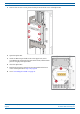
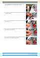
Installing CAP Ms 3 Remove the six neck screws (shown below) from the front cover of the Splice Box. 4 Open the Splice Box. 5 Attach an M4 x 25 pan-head screw to the upper hole, and a second M4 x 25 pan-head to the hole on the lower, left-hand side (shown at right) of the Splice Box. 6 Close the Splice Box. 7 Replace the six neck screws that you removed from the front cover of the Splice Box in Step 3 on page 48. 8 Go to "Grounding the CAP M” on page 49.
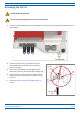
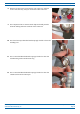
Installing CAP Ms Grounding the CAP M The CAP M must be grounded. Do not use the grounding bolts to connect an external device. 1 Connect an earth-bonding cable to the grounding bolt connections on the outside of the CAP M chassis, as shown below. 2 Loosen the M6 hex nut(s), and then connect the earth-bonding cable between the two washers as shown to the right. 3 4 5 Secure the earth-bonding cable by tightening the M6hex nut(s) that you loosened in the preceding step.
Installing CAP Ms Connect the CAP M Cables Complete the following procedures in the order in which they are presented. Unless otherwise noted, each procedure is applicable to a singular CAP M (not in a cascade), or to a Primary or Secondary CAP M in a cascade.
Installing CAP Ms Connect the CAP M to an RF Antenna The following sections guide you through connecting the CAP M; complete these procedures in the order in which they are presented. • "Clean the RF Cable Connectors” on page 51 • "Connect the Antenna Cable(s)” on page 54. Clean the RF Cable Connectors This section tells you how to clean RF cable connectors. The graphics in this section illustrate the cleaning procedure and do not show the CAP M. This procedure requires the use of compressed air.
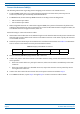
Installing CAP Ms 3 Use compressed air to remove metal chips and small particles from the mating and inner surfaces of the connector. 4 Use a lint-free wipe drenched with isopropyl alcohol to clean the connector winding. 5 Use a cotton bud drenched with isopropyl alcohol to clean the lip of the inner ring. 6 Use a cotton bud drenched with isopropyl alcohol to clean the inside surface of the inner ring.
Installing CAP Ms 8 Remove the protective caps from the unit connector, and then clean it the same way that you cleaned the cable connector. 9 Use compressed air to remove metal chips and small particles from the mating and inner surfaces of the connector. 10 Use a lint-free wipe drenched with isopropyl alcohol to clean the winding area. 11 Use a cotton bud drenched with isopropyl alcohol to clean the inside mating surface of the inner ring.
Installing CAP Ms Connect the Antenna Cable(s) The following information regarding antenna mapping and is relevant to all CAP M variants. • For Non-MIMO bands, there is no channel mapping option for the transceiver/antenna port. The transceiver/antenna port relationship is fixed in hardware. • For MIMO bands, the Era GUI maps MIMO channels according to their AP designation: • – AP0 to antenna port ANT1 – AP1 to antenna port ANT2.
Installing CAP Ms Connect the CAP M to a Classic CAN or TEN Connect the CAP M Optical Port 1 as appropriate for this installation. Note the maximum range listed in Table 11. 1 Remove the dust cap from the CAP M Optical Port 1 connector and the connectors on the SMF or MMF. 2 Follow the local cleaning technique to clean the optical port for each SFP+ Module. 3 Clean the connectors on the SMF or MMF following the fiber supplier’s recommendations.
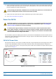
Installing CAP Ms 4 Install an Ethernet OCTIS Kit on the end of the CAT cable that will connect to the Fiber CAP M, and then connect that end of the cable to Port A on the Fiber CAP M. (Refer to the technical data sheet that ships with the OCTIS Kit for further information.) Cat6A, including all Cat6A cables, Cat6A Patch Cords, and Patch Panels, between Port A on the Fiber CAP M and an auxiliary Ethernet device cannot exceed 3 meters (9.8 feet).
Installing CAP Ms CAP M DC Power Cable The standard CAP M DC power cable is a 3.2 m (10.5 ft) 13 AWG cable with a 4-pin Amphenol C016 series plug on one end to connect to the CAP M Mains connector. The other end of the cable is unterminated with 2 end splices to connect to the -48 Vdc power source. The standard DC power cable is shown in Figure 10. Amphenol Protec ve 4-Pin female connector cap 2x end splice Black 4 3 Red 1 CAP M 2 Mains connector Figure 10.
Installing CAP Ms 4 With the cable's Mains plug disconnected from the CAP M, turn the circuit breaker on, unscrew the plug's protective cover, and carefully test the plug with a voltmeter to ensure that the voltage and polarity are correct. 5 Once the testing has been completed, turn off the circuit breaker. 6 Unscrew the protective cover from the Mains connector of the unit. 7 Insert the AC or DC power cable into the Mains connector as shown below; tighten the clamping ring until it is hand tight.
Installing CAP Ms Power the CAP M The CAP M is powered on as soon as power is connected to it. Under normal operating conditions, the Power LED turns on briefly when the unit is first detected. It will then go out briefly, followed by an initialization period during which the Power LED flashes slowly while the CAP M is configured. The Power LED remains a steady green (not flashing) once the unit reaches a fully operational state, which typically occurs within 45 seconds.
Contacting CommScope C ONTACTING C OMM S COPE The following sections tell you how to contact CommScope for additional information or for assistance. CMS Global Technical Support The following sections tell you how to contact the CommScope Mobility Solutions (CMS) Technical Support team. Support is available 7 days a week, 24 hours a day. Telephone Helplines Use the following Helpline telephone numbers to get live support, 24 hours a day: 24x7 +1 888-297-6433 (Toll free for U.S.
Contacting CommScope Hardware to Software Mapping Information 1 Scan the QR Code to the right to view or download the minimum software requirements for each of the DCCS hardware modules. Alternatively, you can go to the following web address to access the portal: http://www.commscope.com/collateral/DCCS_HW_SW_Mapping/ 2 Click on a document link to open it, or right click on the link and select the Save target as… option from the contextual menu.
Contacting CommScope Accessing CommScope Era Series User Documentation 1 Scan the QR Code to the right to go directly to the CommScope DCCS Customer Portal, where you can access the DCCS user documentation. Alternatively, you can go to the following web address to access the portal: https://www.mycommscope.com 2 Access to the Customer Portal requires a user account and password.