CommScope Era™ Medium Power Carrier Access Point Installation Guide • M0201AJE_uc • February 2020
DISCLAIMER This document has been developed by CommScope, and is intended for the use of its customers and customer support personnel. The information in this document is subject to change without notice. While every effort has been made to eliminate errors, CommScope disclaims liability for any difficulties arising from the interpretation of the information contained herein.
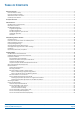
TABLE OF CONTENTS Document Overview .................................................................................................................................................................................. 1 Document Revision History .............................................................................................................................................................................. 1 Document Cautions and Notes.................................................................
Power the CAP M............................................................................................................................................................................................ 57 CAP M AC Power Cable ............................................................................................................................................................................ 57 CAP M DC Power Cable .......................................................................................
D OCUMENT O VERVIEW This installation guide provides a product overview of and installation instructions for the Medium Power Carrier Access Point (CAP M), which allows transmission between CommScope Era™ equipment, antennas, and Ethernet devices (such as WiFi and IP cameras). Table 1 lists the CAP M models that this installation guide supports. Table 1.
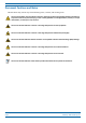
Document Overview Document Cautions and Notes This document may contain any of the following notes, cautions, and warning icons. The icon to the left is used to indicate a caution or warning. Cautions and warnings indicate operations or steps that could cause personal injury, induce a safety problem in a managed device, destroy or corrupt information, or interrupt or stop services. The icon to the left indicates a caution or warning that pertains to laser equipment.
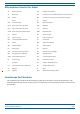
Document Overview Abbreviations Used in this Guide AC Alternating Current GUI Graphical User Interface AP Access Point ISDE Innovation, Sciences et Développement économique Canada AUX Auxiliary ISED Innovation, Science and Economic Development Canada C Celsius kg Kilogram CAN Central Area Node LED Light Emitting Diode CAP H Carrier Access Point, High Power MHz Megahertz CAP L Carrier Access Point, Low Power mm Millimeter CAP M Carrier Access Point, Medium Power MMF Multi-Mode
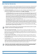
Era System Overview E RA S YSTEM O VERVIEW CommScope Era™ coordinates wireless capacity throughout the entire coverage area via a single centralized head-end location or from an operator’s existing C-RAN hub. Era systems bring together licensed wireless and power, plus Gigabit Ethernet for WiFi into one wireless system that can scale to building size and is technology and spectrum agnostic and adaptive. An Era system comprises the components listed below.
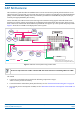
CAP M Overview CAP M O VERVIEW This installation guide describes the Medium Power Carrier Access Point (CAP M), which interfaces via an optical link with a Classic CAN, or with a TEN. This allows the CAP M to provide data over Single-Mode Fiber (SMF), or Multi-Mode Fiber (MMF). Power for CAP Ms is provided over embedded AC/DC (AC version) or remotely through hybrid fiber (DC version). On the downlink, the CAP M converts data arriving at the CAP M to analog signals and sends them to the Antenna port.
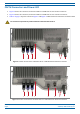
CAP M Overview CAP M Connectors and Power LED • Figure 2 shows the connectors and Power LED on a CAP M that has one antenna connector. • Figure 3 shows the connectors and Power LED on a CAP M that has two antenna connectors. • Table 2 on page 7 maps the callouts in Figure 2 and Figure 3 and describes the connectors and Power LED. Do not remove caps from any of the connectors until instructed to do so. 1 2 3 4 5a 6 7 Figure 2.
CAP M Overview Table 2. Function of the CAP M Connectors and LED REF # Label Description 1 A RJ45 Connects to external Ethernet devices such as WiFi and IP cameras. Cabling is via the appropriate Auxiliary port CAT cable for the protocol; this model supports a 1000 BASE-T and 802.3at Class 3 Power over Cat6A Ethernet connection. Maximum attached cable length is 3 meters (9.8 feet). For information on the Auxiliary port in cascades, see "CAP M Installation and Cascade Rules” on page 17.
CAP M Overview Notch-Filter Connectors The CAP M 7E/80-85/17E/19 has two Notch-Filter connectors that are reserved for future use. The connectors, which are closed by a jumper, have a protective cover. Do not remove the protective cover or interfere with the jumper. Protec ve cover over the Notch-Filter connectors Notch-Filter connectors closed with a jumper Figure 4.
CAP M Overview Dual Mounting Bracket The Dual Mounting Bracket (CommScope PN 7821954-xx) provides the mounting brackets required to mount two CAP Ms back-to-back in a single bracket, which is then mounted to a wall or other vertical, flat surface. See "Mount Two CAP Ms Using a Dual Mounting Bracket” on page 35. Pole Mounting Kit for Up to 18" Poles The CAP M Pole Mounting Kit for Up to 18" Poles (CommScope PN 7692096-XX) is used to mount a CAP M to a pole with a circumference of 4" to 18" (10.2 cm to 45.
Safely Working with Era Hardware S AFELY W ORKING WITH E RA H ARDWARE The following sections provide important information that you should read and know before working with any Era hardware. Observe all cautions and warnings listed in this section. RF Safety Cautions This system is a RF Transmitter and continuously emits RF energy. Maintain a minimum 43.3-inch (110 cm) clearance from the antenna while the system is operating. Whenever possible, shut down the RAN before servicing the antenna.
Safely Working with Era Hardware Property Damage Warnings Keep operating instructions within easy reach and make them available to all users. Only license holders for the respective frequency range are allowed to operate this unit. Read and obey all the warning labels attached to the unit. Make sure that all warning labels are kept in a legible condition. Replace any missing or damaged labels.
Safely Working with Era Hardware General Installation Safety Requirements Wet conditions increase the potential for receiving an electrical shock when installing or using electrically powered equipment. To prevent electrical shock, never install or use electrical equipment in a wet location or during a lightning storm. This system is a RF Transmitter and continuously emits RF energy. Maintain a minimum 8-inch (20 cm) clearance from the antenna while the system is operating.
Safely Working with Era Hardware Compliance 1 Notice: For installations, which have to comply with FCC RF exposure requirements, the antenna selection and installation must be completed in a way to ensure compliance with those FCC requirements.
Safely Working with Era Hardware Antenna Stmt for ISED: This device has been designated to operate with the antennas having a maximum gain of 7 dBi. Antennas having a gain greater than 7 dBi are prohibited for use with this device without consent by ISED regulators. The required antenna impedance is 50 ohms.
Safely Working with Era Hardware 5 Notice: The maximum antenna gain allowed per band for a CAP M 6/6/7E/7E is listed in Table 4 below. Table 4. Maximum Antenna Gain CAP M 6/6/7E/7E FREQUENCY BAND (MHz) POWER (dBm) LINEAR ANTENNA GAIN (dBi) CROSS-POLARIZED ANTENNA GAIN (dBi) 617.0 - 652.0 29 7* 10* 729.0 - 746.0 29 7* 10* 746.0 - 756.0 29 7* 10* 758.0 - 768.
Safely Working with Era Hardware 9 • Reorient or relocate the receiving antenna. • Increase the separation between the equipment and receiver. • Connect the equipment into an outlet on a circuit different from that to which the receiver is connected. • Consult the dealer or an experienced radio/TV technician for help. Notice: For a Class A digital device or peripheral.
Installing CAP Ms I NSTALLING CAP M S The following sections guide you through the installation of a CAP M. Pay attention to all cautions and follow the steps in the order presented. CAP M APs require the use of RFD Card PN 7633229-01 or 7633229-02 or higher. CAP M Installation and Cascade Rules When cascading a Secondary CAP M or an external Ethernet device such as WiFi or an IP camera, you must observe the following rules.
Installing CAP Ms Cat6A Cable Requirements for Ethernet Devices If you connect an Ethernet device to a Fiber CAP M, you must observe the following rules. • Plenum rated cable must be used whenever it is required by local electrical codes. • Shielded twisted pair is not required unless operating in a high RFI/EMI environment. • CommScope strongly recommends using factory terminated and tested Cat6A Patch Cord.
Installing CAP Ms Determine the Power Consumption of the CAP M Use the power consumption matrix in Table 6 to calculate power consumption for a CAP M, where • the consumption numbers are at the CAP M power inputs and do not account for feed losses • the maximum consumption numbers in Table 6 do not include the power consumed by any attached auxiliary devices. Both CAP M power consumption and auxiliary device power must be included when calculating feed losses. Table 6.
Installing CAP Ms Determine the Mounting Site When deciding on a suitable mounting site, observe the following rules; refer also to "Mounting Orientation” on page 28. • The CAP M is suitable for installation indoors or outdoors. • Use the weights listed in Table 7 to determine a site that can bear the weight of the CAP M that is being installed, where: – The “Maximum Lift Weight” is the highest weight that must be lifted during installation.
Installing CAP Ms 502 mm (19.74”) 175 mm (6.88”) 566 mm (22.27”) Figure 5. Mounting Dimensions with the Single Mounting Bracket M0201AJE_uc © February 2020 CommScope, Inc.
Installing CAP Ms 502 mm (19.74”) 309 mm (12.16”) 565 mm (22.26”) Figure 6. Mounting Dimensions with the Dual Mounting Bracket CommScope Era™ Medium Power Carrier Access Point Installation Guide Page 22 M0201AJE_uc © February 2020 CommScope, Inc.
Installing CAP Ms Unpack and Inspect the CAP M and Optional Accessories 1 Inspect the exterior of the shipping container(s) for evidence of rough handling that may have damaged the components in the container. 2 Unpack each container while carefully checking the contents for damage and verify with the packing slip. 3 If damage is found or parts are missing, file a claim with the commercial carrier and notify CommScope Technical Support (see "CMS Global Technical Support” on page 61).
Installing CAP Ms 5 From the Hybrid Fiber Splice Box Kit, insert Fiber Patch Cord in one of the cable glands indicated in the graphic to the right. 6 Strip the insulation of the composite cable for 100 cm and the fibers for 90 cm, and then shorten the copper cables to 25 cm. 7 Insert the composite cable in the first cable gland and separate the multi-fibers cable from the copper wires. It is necessary to remove the nut to perform this action.
Installing CAP Ms 10 If a second splice holder is needed, it can be assembled using the M4 insulating washer and two M4 plain washers, as shown to the right. The required screw is a PTK30 x 12. 11 Remove the sealing nut and rubber of the cable gland and insert the optical cables. 12 Place each cable into one of the grooves of the seal insert. 13 Press the seal insert into the clamp ring opening. 14 Fix the optical cables inside the box using one cable tie and tight the sealing nut.
Installing CAP Ms 17 Insert the copper wires in the first multiple terminal connectors. See markings on the internal support. Then fasten the copper cables inside the box using one cable tie. 18 Remove the sealing nut and insert the CAP M supply cable and tighten the sealing nut. 19 Connect the supply cable to the terminal strip and fix it inside the box using one cable tie. In the instance when two CAP Ms are in a dual mount or a cascade, it is possible to connect a second power supply cable.
Installing CAP Ms Mount the CAP M The CAP M is suitable for indoor and outdoor installations. General Mounting Cautions The following cautions apply to all CAP M installations; there may be other mounting cautions applicable to a specific mounting option, which will be defined in the applicable mounting procedure. Attach all CAP Ms securely to a stationary object as described in this installation guide. To maintain proper ventilation, keep at least 76 mm (3-inch) clearance around the CAP M.
Installing CAP Ms Mounting Orientation CAP Ms are passively cooled and must therefore always be mounted with its ANT port pointing down, as shown in Figure 7. ANT port poin ng down Figure 7. Mounting Orientation for a CAP M CommScope Era™ Medium Power Carrier Access Point Installation Guide Page 28 M0201AJE_uc © February 2020 CommScope, Inc.
Installing CAP Ms Mount the CAP M to a Wall or Vertical Surface There are two mounting options for the CAP M; follow the procedure that is appropriate for this installation: • "Mount a CAP M Using a Single Mounting Bracket” on page 29 • "Mount Two CAP Ms Using a Dual Mounting Bracket” on page 35. If this installation requires the optional Hybrid Fiber Splice Box to provide fiber and power to the CAP M, follow the steps in "Wire an Optional Hybrid Fiber Splice Box” on page 23.
Installing CAP Ms 6 Secure the Mounting Bracket to the wall (or another suitable vertical surface) as shown below. a Install the mounting bracket using 4 M6 screw anchors (not included) or suitable lag bolts according to the drilling layout. The M6 screw anchors do not ship with the CAP M as the anchor type is dependent on the on-site conditions (wall structure and materials). Use screw anchors that are rated for the mounting surface.
Installing CAP Ms 7 From both sides of the CAP M: a Loosen the M6 pins, leaving its washer in place. b Remove the two M6 screws and their M6 plain and M6 split-lock washers; reserve the screws and washers as you will later reinstall them. Loosen the M6 pin Remove the M6x12 screw and its washers M6 plain washer M6 split-lock washer M6x12 screw M0201AJE_uc © February 2020 CommScope, Inc.
Installing CAP Ms 8 Use both handles on the CAP M to lift it above the Mounting Bracket, and then lower it into place. The M6 pins that you loosened in Step 7 on page 31 must align with the Mounting Bracket slots, as shown below. CommScope Era™ Medium Power Carrier Access Point Installation Guide Page 32 M0201AJE_uc © February 2020 CommScope, Inc.
Installing CAP Ms 9 On the right side of the CAP M, slide a washer over the threaded M6 pin, and then secure the CAP M to the Mounting Bracket by torquing the M6 pin to 11 N-m. Align the M6 pins with the Moun ng Bracket slots 10 Repeat Step 9 on the left side of the CAP M. M0201AJE_uc © February 2020 CommScope, Inc.
Installing CAP Ms 11 On lower right of the CAP M, reinstall the M6x12 screw and its washers that you removed in Step 7 on page 31. a Slide first the M6 plain washer and then the M6 split-lock washer over the M6x12 screw. b Insert the M6x12 screw through the screw hole shown below, and screw it back into the CAP M chassis; torque to 11 N-m. M6x12 screw and washer set 12 Repeat Step 11 on the left side of the CAP M.
Installing CAP Ms Mount Two CAP Ms Using a Dual Mounting Bracket In this procedure you will mount two CAP Ms back-to-back in one Dual Mounting Bracket. The steps in this procedure will identify the two CAP Ms as CAP M-1 and CAP M-2, as shown in Figure 8. CAP M 1 (front of the CAP M-1 faces the moun ng surface) CAP M 2 (front of CAP M-2 faces out, and is back-to-back with CAP M 1) Figure 8. Two CAP Ms Back-to-Back in a Dual Mounting Bracket Do the following to mount two CAP Ms in a Dual Mounting Bracket.
Installing CAP Ms 3 Refer to "Determine the Mounting Site” on page 20 to determine the mounting location, which must be able to support the weight and dimensions of the CAP M. Installer must verify that the mounting surface will safely support the combined load of the electronic equipment and all attached hardware and components. 4 Refer to "Mounting Orientation” on page 28 to determine the mounting orientation of the CAP M.
Installing CAP Ms 7 From both sides of CAP M-1: a Loosen the M6 pins, leaving its washer in place. b Remove the two M6 screws and their M6 plain and M6 split-lock washers; reserve the screws and washers as you will later reinstall them. Loosen the M6 pin Remove the M6x12 screw and its washers M6 plain washer M6 split-lock washer M6x12 screw M0201AJE_uc © February 2020 CommScope, Inc.
Installing CAP Ms 8 Use both handles on the CAP M-1 chassis to lift it above the Mounting Bracket, and with the front of the chassis facing the mounting surface, lower it into place. • The M6 pins that you loosened in Step 7 on page 37 must align with the Mounting Bracket slots, as shown below. • The washer for each M6 pin should be next to the CAP M-1 chassis (inside the bracket).
Installing CAP Ms 11 On lower right of the CAP M-1, reinstall the M6x12 screw and its washers that you removed in Step 7 on page 37. a Slide first the M6 split-lock washer and then the M6 plain washer over the M6x12 screw. b Insert the M6x12 screw through the screw hole shown below, and screw it back into the CAP M-1 chassis; torque to 11 N-m. M6x12 screw and washer set in hole closest to the moun ng surface 12 Repeat Step 11 on the left side of the CAP M-1.
Installing CAP Ms 13 From both sides of CAP M-2: a Loosen the M6 pins, leaving its washer in place. b Remove the two M6 screws and their washers; reserve the screws and washers as you will later reinstall them. Loosen the M6 pin Remove the M6 screw and its washer CommScope Era™ Medium Power Carrier Access Point Installation Guide Page 40 M0201AJE_uc © February 2020 CommScope, Inc.
Installing CAP Ms 14 Use both handles on the CAP M-2 chassis to lift it above the Mounting Bracket with the back of its chassis facing the back of CAP M-1, and then lower it into place. • The M6 pins that you loosened in Step 13 on page 40 must align with the Mounting Bracket slots, as shown below. • The washer for each M6 pin should be next to the CAP M-2 chassis (inside the bracket).
Installing CAP Ms 17 On lower right of the CAP M-2, reinstall the M6x12 screw and its washers that you removed in Step 13 on page 40. a Slide first the M6 split-lock washer and then the M6 plain washer over the M6x12 screw. b Insert the M6x12 screw through the screw hole shown below, and screw it back into the CAP M chassis; torque to 11 N-m. M6x12 screw and washer set in hole furthest from the moun ng surface 18 Repeat Step 11 on the left side of CAP M-2.
Installing CAP Ms Mount the CAP M to a 4" to 18" Pole This procedure is specific to the CAP M Pole Mounting Kit for Up to 18" Poles (CommScope PN 7692096-XX), which is used when mounting a CAP M to a pole with a circumference of 4" to 18" (10.2 cm to 45.8 cm). Figure 9 shows the assembled kit mounted to a pole. 4" to 18" (10.2 cm to 45.
Installing CAP Ms 3 Follow the steps in "Unpack and Inspect the CAP M and Optional Accessories” on page 23. Table 10 lists the parts that ship with the CAP M Pole Mounting Kit for Up to 18" Poles. Table 10.
Installing CAP Ms 9 Attach four of the threaded bolts to the side of the top Pole-Mounting Bracket that will face toward the pole (inside the Pole-Mounting Bracket). Install the M8 nut and washers in the order shown. a Slide one M8 plain washer (9A) to one end of each of the four threaded bolts. b Slide an M8 Hexagon Nut (9B) next to the M8 plain washer. c 10 11 12 9A 4" to 18" (10.2 cm to 45.8 cm) Threaded bolts 9B Torque the M8 Hexagon Nut to 27 N-m.
Installing CAP Ms Attach a Hybrid Fiber Splice Box to the CAP M The steps in this section pertain only to those installations that require the use of the optional Hybrid Fiber Splice Box to provide fiber and power to the CAP M. If the optional Hybrid Fiber Splice Box is not required for this installation, skip to "Grounding the CAP M” on page 50.
Installing CAP Ms 2 Remove the six neck screws (shown below) from the front cover of the Splice Box. 3 Open the Splice Box. 4 Attach an M4 x 25 pan-head screw to the upper hole, and a second M4 x 25 pan-head to the hole on the lower, right-hand side of the Splice Box. 5 Close the Splice Box. 6 Replace the six neck screws that you removed from the front cover of the Splice Box in Step 2 on page 47. 7 Go to "Grounding the CAP M” on page 50. M0201AJE_uc © February 2020 CommScope, Inc.
Installing CAP Ms Attaching a Hybrid Fiber Splice Box for a Dual Mount Installation 1 Break the left-hand side hook of the Splice Box bracket. This is necessary for proper mounting. 2 Hang the Splice Box onto the Dual Mounting Bracket on the left-hand side of the CAP M, as shown below. Dual Moun ng Bracket Hybrid Fiber Splice Box CommScope Era™ Medium Power Carrier Access Point Installation Guide Page 48 M0201AJE_uc © February 2020 CommScope, Inc.
Installing CAP Ms 3 Remove the six neck screws (shown below) from the front cover of the Splice Box. 4 Open the Splice Box. 5 Attach an M4 x 25 pan-head screw to the upper hole, and a second M4 x 25 pan-head to the hole on the lower, left-hand side (shown at right) of the Splice Box. 6 Close the Splice Box. 7 Replace the six neck screws that you removed from the front cover of the Splice Box in Step 3 on page 49. 8 Go to "Grounding the CAP M” on page 50.
Installing CAP Ms Grounding the CAP M The CAP M must be grounded. Do not use the grounding bolts to connect an external device. 1 Connect an earth-bonding cable to the grounding bolt connections on the outside of the CAP M chassis, as shown below. Grounding bolts 2 3 4 5 Loosen the M6 hex nut(s), and then connect the earth-bonding cable between the two washers as shown to the right. Secure the earth-bonding cable by tightening the M6hex nut(s) that you loosened in the preceding step.
Installing CAP Ms Connect the CAP M Cables Complete the following procedures in the order in which they are presented. Unless otherwise noted, each procedure is applicable to a singular CAP M (not in a cascade), or to a Primary or Secondary CAP M in a cascade.
Installing CAP Ms Connect the CAP M to an RF Antenna The following sections guide you through connecting the CAP M; complete these procedures in the order in which they are presented. • "Clean the RF Cable Connectors” on page 52 • "Connect the Antenna Cable(s)” on page 55. Clean the RF Cable Connectors This section tells you how to clean RF cable connectors. The graphics in this section illustrate the cleaning procedure and do not show the CAP M. This procedure requires the use of compressed air.
Installing CAP Ms 3 Use compressed air to remove metal chips and small particles from the mating and inner surfaces of the connector. 4 Use a lint-free wipe drenched with isopropyl alcohol to clean the connector winding. 5 Use a cotton bud drenched with isopropyl alcohol to clean the lip of the inner ring. 6 Use a cotton bud drenched with isopropyl alcohol to clean the inside surface of the inner ring.
Installing CAP Ms 8 Remove the protective caps from the unit connector, and then clean it the same way that you cleaned the cable connector. 9 Use compressed air to remove metal chips and small particles from the mating and inner surfaces of the connector. 10 Use a lint-free wipe drenched with isopropyl alcohol to clean the winding area. 11 Use a cotton bud drenched with isopropyl alcohol to clean the inside mating surface of the inner ring.
Installing CAP Ms Connect the Antenna Cable(s) The following information regarding antenna mapping and is relevant to all CAP M variants. • For Non-MIMO bands, there is no channel mapping option for the transceiver/antenna port. The transceiver/antenna port relationship is fixed in hardware. • For MIMO bands, the Era GUI maps MIMO channels according to their AP designation: • – AP0 to antenna port ANT1 – AP1 to antenna port ANT2.
Installing CAP Ms Connect the CAP M to a Classic CAN or TEN Connect the CAP M Optical Port 1 as appropriate for this installation. Note the maximum range listed in Table 11. 1 Remove the dust cap from the CAP M Optical Port 1 connector and the connectors on the SMF or MMF. 2 Follow the local cleaning technique to clean the optical port for each SFP+ Module. 3 Clean the connectors on the SMF or MMF following the fiber supplier’s recommendations.
Installing CAP Ms 4 Install an Ethernet OCTIS Kit on the end of the CAT cable that will connect to the Fiber CAP M, and then connect that end of the cable to Port A on the Fiber CAP M. (Refer to the technical data sheet that ships with the OCTIS Kit for further information.) Cat6A, including all Cat6A cables, Cat6A Patch Cords, and Patch Panels, between Port A on the Fiber CAP M and an auxiliary Ethernet device cannot exceed 3 meters (9.8 feet).
Installing CAP Ms CAP M DC Power Cable The standard CAP M DC power cable is a 3.2 m (10.5 ft) 13 AWG cable with a 4-pin Amphenol C016 series plug on one end to connect to the CAP M Mains connector. The other end of the cable is unterminated with 2 end splices to connect to the -48 Vdc power source. The standard DC power cable is shown in Figure 11. Amphenol Protec ve 4-Pin female connector cap 2x end splice Black 4 3 Red 1 CAP M 2 Mains connector Figure 11.
Installing CAP Ms 4 With the cable's Mains plug disconnected from the CAP M, turn the circuit breaker on, unscrew the plug's protective cover, and carefully test the plug with a voltmeter to ensure that the voltage and polarity are correct. 5 Once the testing has been completed, turn off the circuit breaker. 6 Unscrew the protective cover from the Mains connector of the unit. 7 Insert the AC or DC power cable into the Mains connector as shown below; tighten the clamping ring until it is hand tight.
Installing CAP Ms Power the CAP M The CAP M is powered on as soon as power is connected to it. Under normal operating conditions, the Power LED turns on briefly when the unit is first detected. It will then go out briefly, followed by an initialization period during which the Power LED flashes slowly while the CAP M is configured. The Power LED remains a steady green (not flashing) once the unit reaches a fully operational state, which typically occurs within 45 seconds.
Contacting CommScope C ONTACTING C OMM S COPE The following sections tell you how to contact CommScope for additional information or for assistance. CMS G LOBAL T ECHNICAL S UPPORT The following sections tell you how to contact the CommScope Mobility Solutions (CMS) Technical Support team. Support is available 7 days a week, 24 hours a day. Telephone Helplines Use the following Helpline telephone numbers to get live support, 24 hours a day: 24x7 +1 888-297-6433 (Toll free for U.S.
Hardware to Software Mapping Information H ARDWARE TO S OFTWARE M APPING I NFORMATION 1 Scan the QR Code to the right to view or download the minimum software requirements for each of the DCCS hardware modules. Alternatively, you can go to the following web address to access the portal: http://www.commscope.com/resources/in-building-wireless 2 Click on a document link to open it, or right click on the link and select the Save target as… option from the contextual menu.
Accessing Era User Documentation A CCESSING E RA U SER D OCUMENTATION 1 Scan the QR Code to the right to go to the CommScope DCCS Customer Portal, where you can access the DCCS user documentation. Alternatively, you can go to the following web address to access the portal: http://www.commscope.com/membership 2 Access to the Customer Portal requires a user account and password.
Accessing Era User Documentation CommScope Era™ Medium Power Carrier Access Point Installation Guide Page 64 M0201AJE_uc © February 2020 CommScope, Inc.