
Installation Guide

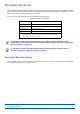
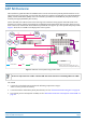
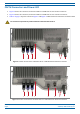
Table Of Contents
- Table of Contents
- Document Overview
- Era System Overview
- CAP M Overview
- Safely Working with Era Hardware
- Installing CAP Ms
- CAP M Installation and Cascade Rules
- Cat6A Cable Requirements for Ethernet Devices
- Prepare for Installation
- Wire an Optional Hybrid Fiber Splice Box
- Mount the CAP M
- Grounding the CAP M
- Connect the CAP M Cables
- Power the CAP M
- Contacting CommScope
- CMS Global Technical Support
- Waste Electrical and Electronic Equipment Recycling
- Hardware to Software Mapping Information
- CMS Technical Training
- Accessing Era User Documentation

CommScope Era
™
Medium Power Carrier Access Point Installation Guide M0201AJE_uc
Page 6 © February 2020 CommScope, Inc.
CAP M Overview
CAP M Connectors and Power LED
• Figure 2 shows the connectors and Power LED on a CAP M that has one antenna connector.
• Figure 3 shows the connectors and Power LED on a CAP M that has two antenna connectors.
• Table 2 on page 7 maps the callouts in Figure 2 and Figure 3 and describes the connectors and Power LED.
Do not remove caps from any of the connectors until instructed to do so.
1 2 3 4 5a 76
Figure 2. Location of Connectors and Power LED on a CAP M with One Antenna Connector
1 2 3 4 5a 76
5b
Figure 3. Location of Connectors and Power LED on a CAP M with Two Antenna Connectors