
Installation Guide

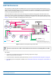
Table Of Contents
- Table of Contents
- Document Overview
- Era System Overview
- CAP M Overview
- Safely Working with Era Hardware
- Installing CAP Ms
- CAP M Installation and Cascade Rules
- Cat6A Cable Requirements for Ethernet Devices
- Prepare for Installation
- Wire an Optional Hybrid Fiber Splice Box
- Mount the CAP M
- Grounding the CAP M
- Connect the CAP M Cables
- Power the CAP M
- Contacting CommScope
- CMS Global Technical Support
- Waste Electrical and Electronic Equipment Recycling
- Hardware to Software Mapping Information
- CMS Technical Training
- Accessing Era User Documentation

CommScope Era
™
Medium Power Carrier Access Point Installation Guide M0201AJE_uc
Page 4 © February 2020 CommScope, Inc.
Era System Overview
ERA SYSTEM OVERVIEW
CommScope Era™ coordinates wireless capacity throughout the entire coverage area via a single centralized
head-end location or from an operator’s existing C-RAN hub. Era systems bring together licensed wireless
and power, plus Gigabit Ethernet for WiFi into one wireless system that can scale to building size and is
technology and spectrum agnostic and adaptive. An Era system comprises the components listed below.
• Ce
ntralAreaNode(CAN)—provides server-level control and primary signal distribution. It combines
the signals from multiple operators and distributes those signals within a venue or multiple venues.
There are two configuration modes available for the CAN: Classic and Switching.
– The ClassicCAN configuration is appropriate for when all the BTS and Baseband so
urces are located
in a centralized space in the same venue as the Classic CAN. You install RF Donor (RFD) Cards and
CPRI Digital Donor (CDD) Cards in a Classic CAN, which digitizes the analog BTS signals from the RFD
Cards and combines those with the BBU CPRI digital signals from the CDD Cards, and then distributes
the RF signals to the TENs. The TENs then provide the RF signals to the Access Points (APs). The
Classic CAN also supports APs that are directly connected to CAT or OPT Cards installed in the Classic
CAN chassis. Wide-area Integration Nodes (WINs) are not supported by a Classic CAN. Users have full
and flexible control of all signal routing via the Era GUI.
– The SwitchingCAN configuration
is appropriate for when WINs are required to allow operators to
bring in baseband signals from multiple remote locations to fully leverage the C-RAN architecture in
their hubs. All operator Baseband signals (analog BTS and BBU CPRI) are supplied to the Switching
CAN by the WINs, so no RFD or CDD Cards can be installed in the Switching CAN. The Switching CAN
then combines the signals from all WINs and distributes those signals to the TENs, and the TENs
provide the signals to the APs. APs are not directly connected to a Switching CAN. Users have full and
flexible control of all signal routing via the Era GUI.
This guide uses “CAN” to collectively refer to Central Area Nodes. When information pertains to a specific
CAN mode, “Classic CAN” and “Switching CAN” will be used.
• Wide-AreaIn
tegrationNode(WIN)—interfaces between a Switching CAN and RF sources, which
makes C-RAN possible in Era by allowing operators to bring in signals from multiple remote locations
kilometers away. You install RFD and CDD Cards in the WIN, which takes the analog BTS signals from the
RFD Cards and combines those with the BBU CPRI digital signals from the CDD Cards, and distributes the
RF sources to a Switching CAN.
• TransportExp
ansionNode(TEN)—is an expansion node connected to the CAN via fiber and can be
located throughout the venue coverage area. A single TEN can support, dependent on the AP type and
powering method, 12 to 32 Access Points (APs), which greatly reduces the number of fiber runs between
the head-end and each AP.
• AccessPoi
nt(AP)—connects a Classic CAN or TEN to antennas or other wireless devices. On the
downlink, an AP converts data arriving at the AP to analog signals and sends them to an antenna. On the
uplink, received signals are digitized and serialized into data streams which are sent back to the Classic
CAN or TEN. APs provide pass-through support for WiFi, IP cameras, or other devices over a common
cable. An AP can be any of the Universal Access Points or Carrier Access Points.
This guide uses “Access Point (AP)” to collectively refer to all versions of the Universal Access Point (UAP)
and the Carrier Access Point (CAP). “Fiber APs” collectively refers to the CAP H, CAP M, and the Fiber
CAP L. When information pertains to a specific AP
type, that AP will be identified.