Part III: Appendices Appendix A Safety Appendix B Installation troubleshooting Appendix C Specifications Appendix D Field Replaceable Units Appendix E guidelines Cable installation and power separation DRAFT
DRAFT
Appendix A Safety This appendix contains specifications for CommScope OneCell, including FCC information and technical data. Radiation Exposure Statement A-2 Human exposure limits for OneCell deployments A-2 DRAFT OneCell® Installation, RP5000 series, Release 4.
Appendix A Safety Radiation Exposure Statement Important: Changes or modifications not expressly approved by CommScope LLC could void your authority to operate the equipment. FCC Part 15 The Baseband Controller and RP5100 have been tested and found to comply with the limits for Class A equipment, pursuant to Part 15 of the FCC Rules. NOTE This equipment has been tested and found to comply with the limits for a Class A digital device, pursuant to part 15 of the FCC Rules.
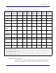
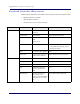
Appendix A Safety Table A-1. RF exposure for OneCell at maximum power internal antennas RPMA5A11B66 RPMA5A11B02 RPMI5A11B01 RPMI5A11B03 RPMI5A11B07 RPMA5A11B12 RPMA5A11B14 RPMA5A11B17 24.13 24.23 24.25 24.00 24.70 21.88 21.45 21.70 Tx Loss (dB) 0 0 0 0 0 0 0 0 Tx Antenna Gain (dBi) 4 4 4 4 4 4 4 4 Transmitter Duty Cycle % 100 100 100 100 100 100 100 100 2 2 2 2 2 2 2 2 Contribution due to multiple antennas (dB) 3.0103 3.0103 3.0103 3.0103 3.0103 3.
Appendix A Safety frequency Electromagnetic Fields, US Federal Communications Commission, Office of Engineering and Technology June 2001. [2] Federal Communications Commission Document OET Bulletin 56, “Questions and answers about biological effects and potential hazards of radio frequency electromagnetic fields”, Federal Communications Commission Office of Engineering and Technology, August 1999.
Appendix B Installation troubleshooting This section contains information on troubleshooting the OneCell installation. It includes the LED patterns for the Baseband Controller and Radio points. Baseband Controller LED patterns B-2 Radio Point LED patterns B-4 DRAFT OneCell® Installation, RP5000 series, Release 4.
Appendix B Installation troubleshooting Baseband Controller LED patterns The Baseband Controller has four LEDs on the front panel.
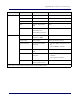
Appendix B Installation troubleshooting LED Display Pattern Indicates Action to Take TIMING LED Green, solid Power On, timing None Amber, solid Self-test failure Replace Baseband Controller Amber, blinking No timing Check GPS antenna connection feed Off Firmware upgrade from DMS None Red, solid* Error in system Replace Baseband Controller Module GPS module down Software/Hardware issues CORE LED Green, solid Power On None Connection to MME Amber, solid Self-test failure Replace Bas
Appendix B Installation troubleshooting Radio Point LED patterns The Radio Point has two LEDs on the front cover, indicators for Radio and PoE+.
Appendix C Specifications This appendix contains specifications for CommScope OneCell, including FCC information and technical data. Electrical ratings and technical data C-2 DRAFT OneCell® Installation, RP5000 series, Release 4.
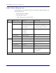
Appendix C Specifications Electrical ratings and technical data The following table lists the electrical ratings and technical data for the Baseband Controller. Operating Environment 0 to 40°C, 10 to 90% relative humidity, indoor use only, not for wet environments Electrical Rating 100 - 230 AC, 2.0A, 50 - 60Hz (auto ranging, no adjustment required) Dimensions 19”w x 1.75”H x 18.8” D (483mm W x 44.4mm H x 477mm D) Weight Single BC 13.1 lbs (5.9 KG), Dual BC 19.1 lbs. (8.
Appendix D Field Replaceable Units This appendix contains instructions for replacing Baseband Controller modules and Radio Points in the OneCell system. FRU overview D-2 Replacing Baseband Controller modules D-2 Replacing Radio Points D-13 Replacing RF modules D-49 DRAFT OneCell® Installation, RP5000 series, Release 4.
Appendix D Field Replaceable Units FRU overview Field Replaceable Units (FRUs) are modules that can be replaced on-site in case of equipment failure. On-site and off-site activities are required when replacing modules. The off-site activities are achieved by using DMS. This appendix contains details for replacing Baseband Controllers (BC) modules and Radio Points (RP).
Appendix D Field Replaceable Units Prerequisite Configuration details for WebGUI commissioning Note: These parameters are derived from the failed unit being replaced. Ethernet cable Note: Required for connecting the laptop to the OneCell Baseband Controller Management port DMS FTP IP address Off-site activities Before replacing the BC module, import a new EDF file to the DMS. This file contains the BC MAC address and HeMs password specific to the new BC.
Appendix D Field Replaceable Units 5 Enter Username and Password. The Search Device screen displays. 6 Enter the device Mac ID. DRAFT The Network Management Portal opens. D-4 7 Select Import tab located in the left margin of the Device console. 8 Select File Import. 9 Browse and select the desired import file. The EDF file format is xml. 10 Click Import. 11 Click Import Progress. Wait for the import to be completed. M0300A2 4.0.
Appendix D Field Replaceable Units 12 Click the Operational History icon in the upper right corner of the page. The Operational History page displays. Check that the file import was successful. OneCell® Installation, RP5000 series, Release 4.0 DRAFT 13 Login to the Device console.
Appendix D Field Replaceable Units 14 Enter the MAC ID of the replacement Baseband Controller. NOTE: Your CommScope service engineer will provide the new BC MAC ID. DRAFT 15 Select the Device configuration tab on the left margin. D-6 16 Configure the same parameters from the BC being replaced. M0300A2 4.0.
Appendix D Field Replaceable Units 17 Select the Dashboard menu item. The Controller will display "Out of Service" until the On-site installation is completed. DRAFT On-site activities After the off-site activities are complete, you are ready to replace the BC module onsite. 1 Power off the OneCell Baseband Controller. OneCell® Installation, RP5000 series, Release 4.
DRAFT Appendix D Field Replaceable Units D-8 2 Make a note of the existing cables connected to the failed OneCell BC. 3 Label the cables identifying the port locations on the BC. Disconnect the cables. 4 Remove the GPS antenna cable from the BC (if applicable). M0300A2 4.0.
Appendix D Field Replaceable Units Turn the mounting screws on the BC front panel counterclockwise to loosen them and remove the BC module. 6 Insert the new BC module into the chassis and tighten the mounting screws. OneCell® Installation, RP5000 series, Release 4.
Appendix D Field Replaceable Units Re-connect the cables as noted in step 3. DRAFT 7 D-10 M0300A2 4.0.
Appendix D Field Replaceable Units 8 Power on the controller. 9 Configure the BC. Follow configuration procedures starting with Accessing the Web GUI on page 6-18. Post-Install Verification On-site Start the verification with Verify the OneCell system installation on page 6-2 and continue through the end of the chapter. Off-site 1 Open a supported Web browser.
Appendix D Field Replaceable Units 2 Enter the IP address for the Device Management portal. http:///deviceconsole DRAFT The Sign In dialog box displays. D-12 3 Enter Username and Password. The Search Device screen displays. 4 Enter the MAC ID of the new BC. The BC Dashboard displays. The Summary at the top of the page should show “Ready.” M0300A2 4.0.
Appendix D Field Replaceable Units NOTE: Provision the remaining Device configurations to align with the failed BC configuration on the DMS Device Configuration page. 5 Scroll to the bottom of the page to view the Device PnP status. If all of the PnP boxes have green checks, the BC replacement is successful. Stop here. If one or more of the PnP boxes are red, those activities failed. Go to the Device PnP page to identify the failed activity.
Appendix D Field Replaceable Units Prerequisite SSH password Replacement OneCell RP module Laptop for Web GUI access Ethernet cable Note: Required for connecting the laptop to the OneCell Baseband Controller Management port On-site activities DRAFT Before replacing the RP, delete the RP from the system using the WebGUI. D-14 1 Connect the Ethernet cable to the MGMT port on the BC’s front panel. 2 Open a supported browser. 3 Enter the IP address for the GUI, using the format below.
Appendix D Field Replaceable Units 4 Ensure the Management Mode tab is selected. The Dashboard displays. DRAFT OneCell® Installation, RP5000 series, Release 4.
DRAFT Appendix D Field Replaceable Units D-16 5 On the Dashboard, click the Radio Points link. The Radio Points Dashboard displays. 6 Click the RP Information tab. 7 If one of the Radio Points is Down, select that RP by checking the box next to it. 8 Click Delete. 9 Check the Radio Point Information table to ensure the RP is deleted. M0300A2 4.0.
Appendix D Field Replaceable Units Replacing a ceiling RP5100i (above tile) 1 Remove the ceiling tile next to the mounted RP to allow access to the mounting hardware and Ethernet cable. 2 Remove the RP cover. DRAFT OneCell® Installation, RP5000 series, Release 4.
Appendix D Field Replaceable Units Disconnect the Ethernet cable. DRAFT 3 D-18 M0300A2 4.0.
Appendix D Field Replaceable Units 4 Replace the cover and twist the RP clockwise to remove it. Set the failed RP aside. DRAFT OneCell® Installation, RP5000 series, Release 4.
Appendix D Field Replaceable Units 5 Attach the mounting plate to the replacement RP. Apply thread locking compound to the screws prior to installation. DRAFT NOTE: D-20 M0300A2 4.0.
Appendix D Field Replaceable Units 6 Attach the RP to the octagonal mounting plate and twist to engage. DRAFT OneCell® Installation, RP5000 series, Release 4.
Appendix D Field Replaceable Units 7 Remove the cover and connect the Ethernet cable to the MR port. The cover is attached to the RP with two lanyards. DRAFT NOTE: D-22 M0300A2 4.0.
Appendix D Field Replaceable Units 8 Attach the plastic cover to the RP. 9 Replace the ceiling tile. DRAFT OneCell® Installation, RP5000 series, Release 4.
Appendix D Field Replaceable Units 10 Verify the RP installation. See The operational state of the RP can be determined by the LED status on the RP. Additional information can be attained from the WebGUI status screens. For verification procedures, see RP post-replacement verification. Replacing a ceiling Indoor RP (on tile) 1 Remove the RP cover. The cover is attached to the RP with two lanyards. DRAFT NOTE: D-24 M0300A2 4.0.
Appendix D Field Replaceable Units 2 Disconnect the Ethernet cable from the RP. DRAFT OneCell® Installation, RP5000 series, Release 4.
Appendix D Field Replaceable Units Replace the cover and twist the RP clockwise and remove the failed RP. DRAFT 3 D-26 M0300A2 4.0.
Appendix D Field Replaceable Units 4 Attach the plate to the replacement RP. NOTE: Apply thread locking compound to the screws prior to installation. DRAFT OneCell® Installation, RP5000 series, Release 4.
Appendix D Field Replaceable Units Attach the RP to the octagonal mounting plate. 6 Secure the RP to the plate by twisting the RP counterclockwise. DRAFT 5 D-28 M0300A2 4.0.
Appendix D Field Replaceable Units 7 Remove the cover and connect the Ethernet cable to the MR port. NOTE: The cover is attached to the RP with two lanyards. DRAFT OneCell® Installation, RP5000 series, Release 4.
Appendix D Field Replaceable Units 8 Attach the plastic cover to the Radio Point. 9 Verify the RP installation. See The operational state of the RP can be determined by the LED status on the RP. Additional information can be attained from the WebGUI status screens. DRAFT For verification procedures, see RP post-replacement verification. D-30 M0300A2 4.0.
Appendix D Field Replaceable Units Replacing a flown mounted RP5100i 1 Remove the RP cover. NOTE: The cover is attached to the RP with two lanyards. DRAFT OneCell® Installation, RP5000 series, Release 4.
Appendix D Field Replaceable Units Disconnect the Ethernet cable. DRAFT 2 D-32 M0300A2 4.0.
Appendix D Field Replaceable Units 3 Replace the cover and twist the RP clockwise. DRAFT OneCell® Installation, RP5000 series, Release 4.
Appendix D Field Replaceable Units Remove the failed RP. DRAFT 4 D-34 M0300A2 4.0.
Appendix D Field Replaceable Units 5 Attach the mounting plate to the RP. NOTE: Apply thread locking compound to the screws prior to installation. DRAFT OneCell® Installation, RP5000 series, Release 4.
Appendix D Field Replaceable Units Attach the RP to the octagon box. DRAFT 6 D-36 M0300A2 4.0.
Appendix D Field Replaceable Units 7 Twist the RP counterclockwise. DRAFT OneCell® Installation, RP5000 series, Release 4.
Appendix D Field Replaceable Units 8 Remove the RP cover. The cover is attached to the RP with two lanyards. DRAFT NOTE: D-38 M0300A2 4.0.
Appendix D Field Replaceable Units 9 Connect the Ethernet cable to the MR port. DRAFT OneCell® Installation, RP5000 series, Release 4.
Appendix D Field Replaceable Units DRAFT 10 Replace the RP cover. D-40 11 Verify the RP installation. See The operational state of the RP can be determined by the LED status on the RP. Additional information can be attained from the WebGUI status screens. For verification procedures, see RP post-replacement verification. M0300A2 4.0.
Appendix D Field Replaceable Units Replacing a pole mounted Indoor RP 1 Remove the RP cover. NOTE: The cover is attached to the RP with two lanyards. DRAFT OneCell® Installation, RP5000 series, Release 4.
Appendix D Field Replaceable Units Disconnect the Ethernet cable. DRAFT 2 D-42 M0300A2 4.0.
Appendix D Field Replaceable Units 3 Loosen the clamp and remove the RP. 4 Attach the bracket to the replacement RP. DRAFT OneCell® Installation, RP5000 series, Release 4.
Appendix D Field Replaceable Units Attach the replacement RP to the pole using the clamp. DRAFT 5 D-44 M0300A2 4.0.
Appendix D Field Replaceable Units 6 Remove the cover and connect the Ethernet cable to the RP. NOTE: The cover is attached to the RP with two lanyards. DRAFT OneCell® Installation, RP5000 series, Release 4.
DRAFT Appendix D Field Replaceable Units D-46 7 Replace the cover on the RP. 8 Verify the RP installation. The operational state of the RP can be determined by the LED status on the RP. Additional information can be attained from the WebGUI status screens. For verification procedures, see RP post-replacement verification. RP post-replacement verification On-site The operational state of the replaced RP can be determined by the LED status on the RP.
Appendix D Field Replaceable Units 2 Open a supported browser. 3 Enter the IP address for the GUI, using the format below. https://:6002 Example: https://192.168.8.1:6002 The Sign In dialog box appears. DRAFT OneCell® Installation, RP5000 series, Release 4.
DRAFT Appendix D Field Replaceable Units D-48 4 Ensure the Management Mode tab is selected. The Dashboard displays. 5 On the Dashboard, click the Radio Points link. The Radio Points Dashboard displays. 6 Click the RP Information tab. The RP Information page displays. M0300A2 4.0.
Appendix D Field Replaceable Units 7 Make sure the replaced RP is UP. Replacing RF modules The following procedures provide instructions for replacing a OneCell Radio Point RF module. WARNING Disconnect the Ethernet cable(s) on the RP to remove the power. Failure to do so will cause damage the RP. 1 Remove the RP cover. DRAFT OneCell® Installation, RP5000 series, Release 4.
DRAFT Appendix D Field Replaceable Units D-50 2 Disconnect the Ethernet cable on the RP. 3 Unscrew the RF module. 4 Remove the RF module. M0300A2 4.0.
Appendix D Field Replaceable Units 5 Install the replacement RF module. 6 Secure it in the slot. DRAFT OneCell® Installation, RP5000 series, Release 4.
Appendix D Field Replaceable Units Connect the Ethernet cable. DRAFT 7 D-52 M0300A2 4.0.
Appendix D Field Replaceable Units 8 Attach the RP cover. 9 Verify the RF module installation. The operational state of the RF module can be determined by the LED status on the RP. Additional information can be attained from the WebGUI status screens. For verification procedures, see RP post-replacement verification. DRAFT OneCell® Installation, RP5000 series, Release 4.
DRAFT Appendix D Field Replaceable Units D-54 M0300A2 4.0.
Appendix E Cable installation and power separation guidelines This section contains best practices for installing Ethernet cables and connecting them to RPs. Overview E-2 Cable handling E-2 Cable termination E-3 Lightning protection E-12 Ceiling connector E-15 Patch panel E-17 Power separation guidelines E-17 DRAFT OneCell® Installation, RP5000 series, Release 4.
Appendix E Cable installation and power separation guidelines Overview When installing Ruggedized RPs, cables that can withstand temperature extremes and inclement weather should be used. In outside environments, avoid contamination or damage to plugs. Plugs must be protected from sunlight and water in a suitable equipment housing or NEMA 4 rated box. It is also important to avoid exposure to water at cut ends of unfilled cables and cords.
Appendix E Cable installation and power separation guidelines Figure E-2. Cable with sock attached using tie wrap Sock Conduit Tie-wrap Feed the sock through the conduit and secure the sock on the terminal end of the cable with the tie-wrap. Once the sock and tie-wrap are in place, pull the cable through the conduit. Cable termination Before installing the Ruggedized RP, terminate the RP end of the Ethernet cable with the RJ45, IP67 connector provided in the box. Figure E-3.
Appendix E Cable installation and power separation guidelines Use the split grommet provided. Once it is in place, coat it with silicone to ensure the connector is sealed. Figure E-4. Assembling the connector on the RP end Cable splicing DRAFT Some cables are run in one piece from source to destination and have connector terminations. In other cases, two shorter pieces of cable need to be spliced together.
Appendix E Cable installation and power separation guidelines 2 Position the filled tube to overlap the end of the inner jacket and seal the gel. Clean off all excess sealant. NOTE: Tape can be used to stabilize the tube for immediate termination before the sealant sets. DRAFT Cable termination Shielded cables must be properly terminated, either grounded or isolated. For exposed installations requiring protection, the end of the shield can be bonded in various ways.
Appendix E Cable installation and power separation guidelines Pull back the jacket along the slit and remove. DRAFT 2 E-6 M0300A2 4.0.
Appendix E Cable installation and power separation guidelines 3 Fold back the foil shielding and drain wire to expose the inner jacket. 4 Prepare the inner jacket for blocking the gel and direct burial. a Cut back the inner jacket b Trim the flute c Clean the excess gel NOTE: The flute can be cut longer to match the blocking tube length. DRAFT OneCell® Installation, RP5000 series, Release 4.
Appendix E Cable installation and power separation guidelines Fill all space inside the tubing with B-sealant and position the filled tube to overlap the end of the inner jacket and seal the gel. 6 Fold the drain wire and foil back over the tube and position the foil to be folded back over the tube. DRAFT 5 E-8 M0300A2 4.0.
Appendix E Cable installation and power separation guidelines An extra piece of foil can be used to cover the foil seam. 8 For an HGS620 termination, wrap the drain wire at least two times around and position it where the spring clips will capture them. 9 Tape over the foil for stability. 10 Trim the wire ends. OneCell® Installation, RP5000 series, Release 4.
Appendix E Cable installation and power separation guidelines Cable grounding For CAT-6A cables, the shield termination method is to use the ground lug and Bbond clip that are available in the 12A1 Grounding Kit. Fold the foil back over the jacket end and wrap the drain wire around the end and push the ground lug over the wrap. DRAFT 1 E-10 M0300A2 4.0.
Appendix E Cable installation and power separation guidelines Open the B-bonding clip to be placed and closed over the grounding lug. 3 The lug tail can be cut off or used for ground attachment. 4 Treat the inner jacket as described in step 4 on page E-7. OneCell® Installation, RP5000 series, Release 4.
Appendix E Cable installation and power separation guidelines For an isolated shield termination, the 1572A and 1592A outer jacket foil and drain wire are removed a short distance back from the termination and electrical tape is used to isolate the foil end. Lightning protection CommScope recommends including lightning protection in your OneCell system to isolate equipment from surge damage.
Appendix E Cable installation and power separation guidelines Figure E-5. CAT6-A lightning protector Outdoor protection The following is an example of a pole mounted CAT-6A configuration for protecting remote equipment installed outdoors. Table E-1 lists the recommended parts for installing the protection equipment. Table E-1.
Appendix E Cable installation and power separation guidelines Figure E-6. Remote equipment protection for outdoor devices NEMA 4x enclosure Back panel Bottom Mounted Liquid Tight Cordgrips Ground Buss Bottom Mounted Liquid Tight Bushing NOTE DRAFT Enclosure should be mounted close to the equipment for the best protection. E-14 M0300A2 4.0.
Appendix E Cable installation and power separation guidelines Figure E-7. Protector box mounted to pole Pole Mount kit Minimize excess cord length DRAFT Ceiling connector If surge protection is not needed, gel flooded cables can be blocked and transitioned to indoor cable using a ceiling connector. The following link is for the recommended CommScope part. Ceiling connector 1 Terminate the indoor cable first – then lay down a bed of B sealant. OneCell® Installation, RP5000 series, Release 4.
Appendix E Cable installation and power separation guidelines Clean all gel from the end of the OSP cable. 3 After the cable and conductors are positioned, fill the area around the cable end with sealant and close the connector housing. DRAFT 2 E-16 M0300A2 4.0.
Appendix E Cable installation and power separation guidelines Patch panel CommScope recommends installing a patch panel in the NOC to connect and manage CAT-6A cables. The following is a list of recommended CommScope 24 and 48 port patch panels and high density information outlets. • 760163436_HFTP-HD6B-1U-24 • 760163444_HFTP-HD6B-2U-48 • 760163451_HFTPA-HD6B-1U-24 • 760163469_HFTPA-HD6B-2U-48 • 760163519_HFTP-J6 • 760163527_HFTP-J10G For more information, go to CommScope.
DRAFT Appendix E Cable installation and power separation guidelines E-18 M0300A2 4.0.
B OneCell® Installation, RP5000 series, Release 4.
DRAFT OneCell® Installation, RP5000 series, Release 4.0 M0300A2 4.0.