
Users Manual Part 2


Appendix B Installation troubleshooting
B-4 M0300A2 4.0.11 January 2020
DR
AFT
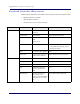
Radio Point LED patterns
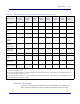
The Radio Point has two LEDs on the front cover, indicators for Radio and PoE+. The
following table shows
• Display pattern for each LED
• What the pattern indicates
• Action to take, if any, to resolve the issue
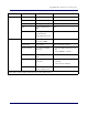
LED Display Pattern Indicates Action to Take
RADIO Green, solid Power On, transmitting None
Amber, solid • RFTxState OFF
• No Controller Assigned
• No Timing
• Check 1588 VLAN configuration
• Verify RP is in STANDBY because
more than
32 RPs are connected
Red, solid • No connection to
Con
troller
•HW error
•Low Power
Hardware error – replace RP module
Green, blinking Firmware upgrade None
Amber, blinking RF module Self-Test Failure Replace RF module
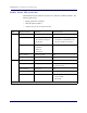
POE+ Green, solid Power On, PoE++ power None
Amber, solid Link up, no power Check that the Ethernet cable is
connected to the RP
Green, blinking PoE+ power None
Amber, blinking Platform Self-Test Failure Replace RP
Red, solid Ethernet port error • Connect the Ethernet cable between
the BC
and RP
• Replace RP
* Note: When all of the LEDs are solid red, there is
an RP hardware failure.