
Users Manual Part 2


Appendix B Installation troubleshooting
B-2 M0300A2 4.0.11 January 2020
D
R
A
F
T
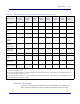
Baseband Controller LED patterns
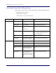
The Baseband Controller has four LEDs on the front panel. The following table shows
• Display pattern for each LED
• What the pattern indicates
• Action to take, if any, to resolve the issue
LED Display Pattern Indicates Action to Take
STATUS Green, solid Power On
Sectors up
None
Amber, solid Self-test failure Replace Baseband Controller
Green, blinking Firmware upgrade from
DMS
Sectors not up
None
Amber, blinking No configuration from DMS • Check DMS availability
• Check if the provisioning is correct
• Escalate to operator
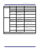
OFF BC rebooting after upgrade None
Red, solid* Error in system - software or
hardware issues detected
Replace Baseband Controller Module
RP ERROR Green, solid Power On None
Amber, solid Self-test failure Replace Baseband Controller
Amber, blinking No Radio Points connected Check RP cable
Off Radio Points connected,
firmware upgrade from
DMS
None
Red, blinking Radio Point alarm - PLL
state unlock; service
impacting alarm from Radio
Point (alarm in one or more
RP)
Check 1588 VLAN configuration