
User Manual

4. INSTALLATION PROCEDURE
4.1 NSPECTION
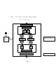
Open the enclosure of the bi-directional amplifier (BDA) and carefully inspect the inside
assembly of the unit.
Verify that all components are properly secured to the base of enclosure, there are no lose
parts, and all interconnections are reliable.
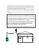
4.2 SITE INSTALLATION
4.2.1 The bi-directional amplifier can be installed as a freestanding unit lying on the shelf
of the cabinet or any other adequately strong support. It can also be secured by screws to
the wall or rack using four holes in the tabs located at the back plate of the enclosure. It is
recommended that the environmental temperature will not exceed 65 C and the area will
be adequately ventilated.
4.2.2 Once amplifier is installed in place, open the front door and verify that all internal
parts are securely mounted.
4.2.3 Connect the ground wire to ground stud on the enclosure.
4.2.4 Plug in the AC cable into the AC socket to turn on the amplifier. The green light on
the enclosure must be lit on.
4.2.5 Connect spectrum analyzer to the input (donor antenna) cable. Measure the signal
level in the cable coming into the Down-link port of the amplifier. If the signal level is
above –40 dBm, add attenuator with the corresponding value or use internal attenuator, if
the BDA option is so equipped.
4.2.6 Repeat the same for the cable that will be connected to the Up-link port of the
amplifier.
4.2.7 Connect the spectrum analyzer via 20 dB pad to the Down-link port of the BDA.
CAUTION
Use caution working with the bi-directional amplifier.
Disconnect the 115 VAC from the amplifier prior to
inspection.