
User Manual
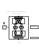

Connect the “donor” side cable to the Up-link port of the BDA. Observe the level of the
amplified signals on the spectrum analyzer. Adjust the gain (if the BDA option is so
equipped) or external (internal, if so equipped) attenuator value to limit the power of the
signals to +23 dBm for CDMA, +26 dBm for GSM, or +25 dBm for TDMA
applications.
4.2.8 Repeat the same measurements connecting the spectrum analyzer to the Up-link
port and cable to the Down-link port. Adjust the level of amplified signals at the Up-link
port to +23 dBm for CDMA, +26 dBm for GSM, or +25 dBm for TDMA applications.
4.2.9 Record the settings of attenuators.
4.2.10 Connect the Up-link cable to the amplifier. Check the security of the installation
and presence of the AC power. Amplifier is ready for operation.
4.3 REMOVE BI-DIRECTIONAL AMPLIFIER
4.3.1 Unplug the AC cord from the socket. AC light on the amplifier must be off.
Disconnect all coaxial cables.
4.3.2 Dismount amplifier from the wall or remove it from the shelf.
4.4 SHIPMENT AND STORAGE OF THE BDA
4.4.1 Use common technical shop practices to ensure equipment protection during
shipment or storage.
4.5 TROUBLESHOOTING AND FAULT DETECTION
4.5.1 Check the presence of the AC power. The AC light must be on.
4.5.2 Check the continuity of all connecting cables.
4.5.3 If the fault was not located, remove the amplifier and send it to the manufacturer for
repair.
4.5.4 RF testing of the amplifier is possible in the specially equipped laboratory.
WARNING!
110 VAC CAN BE LETHAL!
ALWAYS UNPLUG THE AMPLIFIER
BEFORE SERVICING THE INTERIOR.
.