
Manual

1
FL1 LOW PASS FILTERS
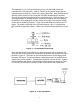
Broadband amplifiers, by definition, provide little, if any, suppression of harmonic
energy. The output of the amplifier will contain harmonics of the input signal.
Thus, if direct operation into an antenna is expected, filtering of the amplifier
output is necessary to meet FCC regulations for spectral purity. A five element,
low pass filter will provide more than sufficient harmonic attenuation. The low
pass filter will attenuate signals above the desired output frequency.
Filter Design
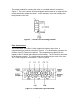
The five element, low pass filter design is derived from information contained in
the ARRL Handbook. The filter schematic is shown in Figure 1. The various
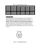
filter parameters are shown in Table 1. The capacitance values derived for C1
and C2 are not standard values for some of the filters. In order to achieve the
closest value for the filter, standard values are placed in parallel. Provision has
been made on the PC board to accommodate the parallel values. When a
capacitance value requires parallel values, the capacitors are identified as C1A
and C1B for the parallel combination of C1. C2A and C2B are the parallel
combination of C2. These combinations are shown in Table 2.
Figure 1 - FL1 Schematic Diagram
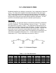
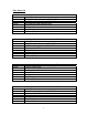
Table 1 – FL1 Filter Parameters
BAND Fcutoff L1,L3 L2 C1,C2
(meters) (MHz) (uH) No. of Turns Toroid (uH) No. of Turns Toroid (pf)
160 2.1 8.1 23 T-106-2 11.4 28 T-106-2 1653
80 4.1 4.1 16 T-106-2 5.8 20 T-106-2 847
40 7.4 2.3 12 T-106-2 3.2 14 T-106-2 470
20 14.450 1.18 9 T-106-6 1.65 11 T-106-6 240
15 21.550 0.79 7 T-106-6 1.11 8 T-106-6 161
10 29.8 0.57 6 T-106-6 0.80 7 T-106-6 117