CNI-G03M Developer's Guide: 1. Overview 2: Specification and features A.Environment B.General RE specifications C Radio interface D. Transmitter E. Receiver. 3. Clitoral guide. 4.
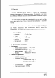
CNI-903M Developer's Guide 1. Overview CNI-903M. Radiogram Packet Modem), is a ‘digital’ data communication equipment in accordance: with Mobility specification.
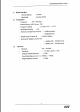
CNIE903M Developer's Guide C.: Radio interface Channel spacing F125KHz Bandwidth so less d D. Transmitter Frequency. £896 +902 MHZ Transmit power (MAX Power : 2W) Frequency stability Modulation stability: 0 23% han [OK Hz Speckle (251 ~ #5510) Harmonic and Spurious Emission; Output Power in carrier off: Spurious RF Radiation Carrier E. Receiver v Frequency Sensitivity ‘Adjacent Chanel Rejection Que-of-Band Rejection (fol Image frequency rejection 7:60dBo( Mobile} + 0.
CHICNESS Developer's Guide 3. Circuit guide A. RE circuit CNIDARIAN: circuit consists of: five parts, cache of which! is power supply, antenna, synthesis / modulation of frequency. transmission and reception. (I): Power supply Power supply is composed of voltage regulator and switching part: Voltage regulator generates IV. of power supplied: from VBE when the ‘control of RF EN switch is warned on.
COMMUNISM: Developer's Guide: {Frequency synthesizer and modulator Frequency synthesizer consists of PLL part, VCO module and per-modulation filter The PLL part 1s composed of phase detector, loop filter, and 12.6Mhz VCTCXO VED module generates: 896~902Mhz frequencies. in recording with the: voltage which is from ‘charge pump'of PLL to loop filter. Programmable Divider in PLL makes the VCO output frequency to any Chanel value according to the frequency data from Logic CPU.
CNI-903M Developer's Guide 455K Hz simultaneously. 24d IF signal of 453K Hz passes Ceramicist filer) tn remove the ‘noise, and the signal is demodulated with discriminator method. Here detected RE signal entered {ito receiver amid RSS signal which indicates the siren, and they are passed 10 micro processor in analogue value, & Transmitter Transmitter consists of driver amp and power amplifier, and TX power control. It generates carrier frequency while share RX with frequency synthesizer.
CNI-903M Developer's Guide @ Modem Data Pump (C7) Modem part is in charge of MASC protocol , and transmits two way Daw between CPU and RE part.
CNI-003M Developer's Guide 2. Pin Assignments of CNI-903M This unit can be easily integrated into anywhere of the wireless modem adopted device. PIN ASSIGNMENTS LEND Ground to Host 2 RX AUDIO LRx Audio 3. OND Ground to Host 4, RTS S Ready to send 8. DSR Hats Sel Ready SECTS “Clear To Send TR {Ring Indicator BRANDT Data Transmit Ready: OG ANGELINE Td Range Indicator 10: 0M = Oni indicator 11 SENSED SENSED 12, MBG 1 Message Wailing 13. SENSES SENSES 14: SENSES S SENSES 15.
CNIDARIAN Development's Guide 3. Power Supply Example of Power Supply from outsource input Voltage is SVE 10%, current is about 2[A].
CNI-903M Developer's Guide ® Design Considerations To integrate a wireless modern; there are several issues: that: need fo: be addressed and considered. Internal connections and placement are critical to a successful implementation: A successful design requires Attention to several support mechanisms as following: = DC Power. = Serial interface and control Mechanical mounting. = Software Sin Antenna RF control 1. Production Applications The OEM wireless modem is well sited for mobile and fixed applications.
CNI-903M Developer's Guide uo Installation Installing CNL903M modem i§ very simple as follows: . Price the modem to connector on product housing, and apply 8 lite force to push it down to be connected. Caution : Care not to bend or damage the connector pins, Use four #2-56 UNC 2A machine screws to fie up the modem as the figure shown below. Connect mode connection cable to a small hole provided at the rear of the modem: Connect the modem connection cable to Antenna 1.
CNI-903M Developer's Guide: Bm Warning Label Following warning {able shall be attached on the devices using CNIDARIAN modem. While this device is in operation, 4 separation distance of at least 20 centimeters (7.87 inches) is mainlined between radiating antenna and the body of the user or nearby persons in order to meet the FCT RF exposure guidelines.
CNLO03M Developer's Guide WM Antenna Specification Product Name : Whip Antenna of 900MHz Ra ripe MODEL : HA-900-MASS Manufacturer : Han kook Antenna Company 4) “Application This specification describes 1/4 WHIP ANTENNA used for frequency mage of SODOMIZE Tor transmission DATA of wireless. Conditions of using Antenna B Handheld W Fixed B Mobile | B Outdoor W Indoor U Others © : Shape of Antenna Refer to attached drawing No.
CNI-903M Developer's Guide @ Other features and performance A. Temperature Antenna shall not ‘be deformed or bandaged and: shall. satisfy “Clause 47 io this specification after Placing Antenna at =30 Can 70°C: for 96 hours. B. Humidity After placing Antenna at surrounding tenpin.
CNL903M Developer's Guide GLEE lea MAG 18 4RC BT Zp UR lpr | Sib Ges Bue rink BEE Tee TT ee Sen Hae and sur < Picture t > Stimulus CH1 MEN Stimulus CH1 MEN [MHz] [dB | {MHz | [dB| 894.000 230 931.000 1178 896.000 Tn 934.000 119.607 999.000 23158 036.000 C1858 901.000 «23.608 939.000 ~17:047 904.000 «23.981 941.000 16.942 906.000 224393 944.000 16216 909.000 224.983 946.000 -15.56 911.000 26.191 949.000 14903 514.000 28439 951.000 14773 916.000 32336 934.000 13.759 919.000 -36:85 956.000 “13.303 921.000 233.
CNI-903M Developer's Guide Ed CHL HIE LFS Leah in Fagin se, he id asm HOG GEE tiny a Tisha Ben IC CENTER RINGTONES OR HE SPAN CA SON ued Mg < Picture 3 > Stimulus CH1 CH1 Stimulus [MHz] | MEN | MEN, | {MHz] | MEN | MEN, 894.000 50.727 7.6973 931.000 44422 6.0938 296.000 51014 7.3359 934.000 44.288 7.9629 899.000 51.324 6:9336 936.000 44.541 9.8516 901.000 51.551 6.5312 939.000 45.236 11.643 904.000 51.783 6.1953 941.000 46.184 13.26 906.000 52.045 58164 944.000 47.193 14.941 809.000 32.516 5.207 946.000 48.
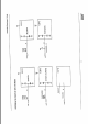
ol mo wipe he poi} =r aio Rook wp capacious 82 woo Ariel B = coal Sw i fen ne wrt Cane ke #161 R21 cus Li cortisol isd RE Lee] 2 Ra R17 mii wl ge cis? Sosa a one asl cus) we Riz] wt O 3Eg 2 CHT.
Key X02 cus ui} Cok foe “1 for cur} £34) fn £32: —Iz Ee 1108 smn oe cif en wel} work] oot RIS id cirri [OT tel font} ane wm cis] cis} civics Q ron nf emf a 2 Lar ssa net 28 os3] wf] coq fou cat Rusher i ref 0 rif potpie 1 0400maph 8
RY freq © 935MHZ-043MH/Z He Hobbit hos-1 = Thu fpr 12 16:41:36 2001 CNI-903M RF SCH. ee Lam Lew freq : B96MHz-902M ig RATE we Lie. Nk: fester nls my + ais i hse 4 ug SEAR Mem scree 58 AE Diem MR SANE BATTLEDRESS SA ar vol AAT HOY ¥ were RLV gio am cn = jig pep Cis C80 CONTRIBUTOR cine.
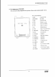
RF Block Diagram LNA ANT x / Gomez to 941MEIZ SAW FILTER BUFFER EOE cotton ] oo DRIVER oe PWM BATTERY — I REGULATOR 2nd LOCAL X-LAT CERAMIC FILTER DISCRIMINATOR TH DATA | | MODEM DATA PUMP METADATA aii m Boy TX Vee HAVOC TL agave veo