Communications Specialties’ Fiberlink® 3370 User’s Manual Broadcast quality 3G/HD/SD-SDI, 10/100 Ethernet and 2 channels of RS-Type data over one single mode or two multimode fibers. All data channels are available simultaneously! Fiberlink® 3370 Series 3G/HD/SD-SDI Transmission and 10/100 Ethernet & 2 Channels of RS-Type Data over one single mode or two multimode fibers. World Headquarters 125 Comac Street Ronkonkoma, New York 11779 USA Tel: (631) 273-0404 Fax: (631) 273-1638 info@commspecial.
Fiberlink® 3370 Series Contents Contents Welcome . . . . . . . . . . . . . . . . . . . . . . . . . . . . . . . . . . . . . . . . . . . . . . . . . . . . . . . . . . . . . . . . . . 3 Features. . . . . . . . . . . . . . . . . . . . . . . . . . . . . . . . . . . . . . . . . . . . . . . . . . . . . . . . . . . . . . . . . . . 3 Package Contents. . . . . . . . . . . . . . . . . . . . . . . . . . . . . . . . . . . . . . . . . . . . . . . . . . . . . . . . . .
Fiberlink® 3370 Series Welcome | Features | Package Contents Welcome Thank you for purchasing Communications Specialties, Inc.’s Fiberlink® 3370 Series. The 3370 Series is used to transmit 3G/HD/SD-SDI over one single mode fiber or two multimode fibers as well as 10/100 Ethernet and two channels of RS-Type data. The Fiberlink 3370 series is compatible with single mode or multimode fiber.
Technical Specifications Fiberlink® 3370 Series Technical Specifications Model Part Number Specification Unit Type Part Number Transmitter Box (1 Fiber, SM) Transmitter Rack Card (1 Fiber, SM) Receiver Box (1 Fiber, SM) Receiver Rack Card (1 Fiber SM) Transmitter Box (2 Fiber, MM) Transmitter Rack Card (2 Fiber, MM) Receiver Box (2 Fiber, MM) Receiver Rack Card (2 Fiber MM) 3370-B7L (LC) 3370-C7L (LC) 3371-B7L (LC) 3371-C7L (LC) 3372-B7L (LC) 3372-C7L (LC) 3373-B7L (LC) 3373-C7L (LC) 3370-B7S (ST) 337
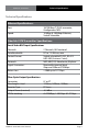
Technical Specifications Fiberlink® 3370 Series Technical Specifications Ethernet Specifications: Port: Speed: 10/100 Base-T, RJ-45 connector, Configured as MDI 10 Mbps & 100 Mbps Ethernet, Switch Selectable Fiberlink 3370 Transmitter Specifications: Serial Video BNC Input Specifications Channels Data Bandwidth Control Format Protocols Signal Connectors: Return Loss 2 Channels, Bi-Directional DC to 115 Kb/sec, max.
Technical Specifications Fiberlink® 3370 Series Technical Specifications Fiberlink 3371 Receiver Specifications: Fiber Optic Input Specifications Connector Wavelength Minimum Input Sensitivity Maximum Input Power LC or ST 1100 - 1620 nm -17 dBm at 2.97 Gbps; -22 dBm at 1.485 Gbps -24 dBm at 270 Mbps; 0 dBm Serial Video BNC Output Specifications Number of Outputs Signal Level DC Offset Rise/Fall Time Overshoot Timing Jitter Alignment Jitter Re-clocking Page 6 1 800mV ± 10% 0V ± 0.5V < 135 ps at 2.
Fiberlink® 3370 Series Operating Loss Budget | Maximum Useable Distance Fiberlink 3371 Receiver Specifications: Operating Loss Budget Single Mode Fiber Multimode Fiber (62.5u) Multimode Fiber (50u) Maximum Useable Distance* Single Mode Fiber Multimode Fiber (62.5u) Multimode Fiber (50u) 0-14 dB at 2.97 Gbps 0-17 dB at 1.485 Gbps 0-20 dB at 270 Mbps 0-14 dB at 2.97 Gbps 0-17 dB at 1.485 Gbps 0-20 dB at 270 Mbps 0-14 dB at 2.97 Gbps 0-17 dB at 1.485 Gbps 0-20 dB at 270 Mbps 30 km at 2.97 Gbps 48 km at 1.
Alarm Switch Settings | Installation Instructions Fiberlink® 3370 Series Alarm Switch Settings & Options The Rack Card version of this product has an additional red indicator LED that illuminates when an alarm condition exists. The rack card unit also provides an output to drive a model 6020A Alarm Sensing Module which provides an audible tone and activates a set of contacts for external signaling purposes.
Installation Instructions Fiberlink® 3370 Series Installation Instructions (cont.) 6) Connect the fiber optic cable(s) to the transmitter and receiver units. Note: when using two fiber version, you must connect the transmitters Optical A to the receivers Optical A and the transmitters Optical B to the receivers Optical B. 7) Connect the Universal Power Supply to the transmitter and receiver units. For box versions using DC power, please refer to figure 1.
Data Configuration (Box Version) Fiberlink® 3370 Series Data Configuration (Box Version): The Fiberlink 3370 Series box units have two dip switch panels, one with 10 switches, one with 9. The first panel, “Data Config A”, represents the Ethernet and RS Channel A configuration. The second panel, “Data Config B”, represents RS Channel B configuration. Note that all data channels are available simultaneously.
Fiberlink® 3370 Series Data Configuration | Baud Rates (Box Version) Baud Rate Configuration E 1 2 3 4 5 6 7 8 9 1 2 3 4 5 6 7 8 9 DATA CONFIG A DATA CONFIG B E 1 2 3 4 5 6 7 8 9 1 2 3 4 5 6 7 8 9 DATA CONFIG A DATA CONFIG B E 1 2 3 4 5 6 7 8 9 1 2 3 4 5 6 7 8 9 DATA CONFIG A DATA CONFIG B E 1 2 3 4 5 6 7 8 9 1 2 3 4 5 6 7 8 9 DATA CONFIG A DATA CONFIG B E 1 2 3 4 5 6 7 8 9 1 2 3 4 5 6 7 8 9 DATA CONFIG A DATA CONFIG B E 1 2 3 4 5 6 7 8 9 1 2 3 4 5 6 7 8 9 DATA CONFIG A DATA CONFIG
Fiberlink® 3370 Series Data Configuration (Box Version) Ethernet Configurations E 1 2 3 4 5 6 7 8 9 1 2 3 4 5 6 7 8 9 100 Base-T Ethernet DATA CONFIG A DATA CONFIG B E 1 2 3 4 5 6 7 8 9 1 2 3 4 5 6 7 8 9 DATA CONFIG A DATA CONFIG B E 1 2 3 4 5 6 7 8 9 1 2 3 4 5 6 7 8 9 DATA CONFIG A DATA CONFIG B E 1 2 3 4 5 6 7 8 9 1 2 3 4 5 6 7 8 9 DATA CONFIG A DATA CONFIG B E 1 2 3 4 5 6 7 8 9 1 2 3 4 5 6 7 8 9 DATA CONFIG A DATA CONFIG B 10 Base-T Ethernet RS-232 RS-485/422 4 Wire RS-485 2 Wire
Data Wiring (Box Version) Fiberlink® 3370 Series Data Wiring: RS-Type data wiring for the Fiberlink 3370 Series is as follows: RS-232 Input G 1 2 3 4 G 1 2 3 4 Channel A Channel B RS-422/485 - 4 Wire Input G 1 2 3 4 G 1 2 3 4 + – Channel A + – Channel B RS-232 Output G 1 2 3 4 G 1 2 3 4 Channel A Channel B RS-422/485 - 4 Wire Output G 1 2 3 4 G 1 2 3 4 + – Channel A + – Channel B RS-485 - 2 Wire Input/Output G 1 2 3 4 G 1 2 3 4 + – Channel A + – Channel B Fiberlink® 3370 Series Us
Data Configuration (Card Version) Fiberlink® 3370 Series Data Configuration (Card Version): The Fiberlink 3370 Series card units have two dip switch panels with 10 switches. The first panel, “DATA CONFIG A”, represents the Ethernet and RS Channel A configuration. The second panel, “DATA CONFIG B”, represents RS Channel B configuration. Note that all data channels are available simultaneously.
Fiberlink® 3370 Series Data Configuration | Baud Rates (Card Version) Baud Rate Configuration 1 2 3 4 5 6 7 8 9 10 1 2 3 4 5 6 7 8 9 10 DATA CONFIG A DATA CONFIG B 1 2 3 4 5 6 7 8 9 10 1 2 3 4 5 6 7 8 9 10 DATA CONFIG A DATA CONFIG B 1 2 3 4 5 6 7 8 9 10 1 2 3 4 5 6 7 8 9 10 DATA CONFIG A DATA CONFIG B 1 2 3 4 5 6 7 8 9 10 1 2 3 4 5 6 7 8 9 10 DATA CONFIG A DATA CONFIG B 1 2 3 4 5 6 7 8 9 10 1 2 3 4 5 6 7 8 9 10 DATA CONFIG A DATA CONFIG B 1 2 3 4 5 6 7 8 9 10 1 2 3 4 5 6 7 8 9 10 DA
Fiberlink® 3370 Series Data Configuration (Card Version) Ethernet Configurations 1 2 3 4 5 6 7 8 9 10 1 2 3 4 5 6 7 8 9 10 DATA CONFIG A DATA CONFIG B 1 2 3 4 5 6 7 8 9 10 1 2 3 4 5 6 7 8 9 10 DATA CONFIG A S1 1 2 3 4 5 6 7 8 9 10 1 2 3 4 5 6 7 8 9 10 DATA CONFIG A DATA CONFIG B 1 2 3 4 5 6 7 8 9 10 1 2 3 4 5 6 7 8 9 10 DATA CONFIG A DATA CONFIG B 1 2 3 4 5 6 7 8 9 10 1 2 3 4 5 6 7 8 9 10 DATA CONFIG A DATA CONFIG B 10 Base-T Ethernet 100 Base-T Ethernet RS-232 RS-485/422 4 Wire RS
Fiberlink® 3370 Series Data Wiring (Card Version) Data Wiring: RS-Type data wiring for the Fiberlink 3370 Series card units is as follows: G 1 2 3 4 Data A G 1 2 3 4 Data B RS-232 Input G 1 2 3 4 RS-232 Output G 1 2 3 4 Data A G 1 2 3 4 Data A G 1 2 3 4 Data B RS-422/485 - 4 Wire Input G 1 2 3 4 Data B RS-422/485 - 4 Wire Output G 1 2 3 4 Data A G 1 2 3 4 Data A G 1 2 3 4 Data B + – Data B + – RS-485 - 2 Wire Input/Output G 1 2 3 4 Data A G 1 2 3 4 Data B + – Fiberlink® 3370 Series
Indicator LEDs Fiberlink® 3370 Series Indicator LEDs The Fiberlink® 3370 Series has several indicator LEDs that are used to monitor the state of the unit. Card versions have an additional Alarm LED. Transmitter LEDs LED Status Definition Power On Indicates that correct power has been applied. 3G Rate Off On Indicates no 3G-SDI data rate lock Indicates 3G-SDI data rate lock at 2.97 Gbps or 2.97/1.
Indicator LEDs Fiberlink® 3370 Series Receiver LEDs LED Status Definition Power On Indicates that correct power has been applied. 3G Rate Off On Indicates no 3G-SDI data rate lock Indicates 3G-SDI data rate lock at 2.97 Gbps or 2.97/1.001 Gbps HD Rate Off On Indicates no HD-SDI data rate lock Indicates HD-SDI data rate lock at 1.485 Gbps or 1.485/1.
Fiberlink® 3370 Series Operating Pointers | Troubleshooting Operating Pointers Remember to check attenuation of the fiber optic cable. The system will only operate properly if these specifications fall within the range of the system’s loss budget. Note: If no signal is applied to the 3370 Transmitter, no optical power will be present on the 3370 Transmitter’s output. Troubleshooting Multimode fiber optic cable contains an optical fiber with a light carrying “core” that is only .0025 inches (62.
Fiberlink® 3370 Series Maintenance and Repairs | Certifications Maintenance and Repairs The Fiberlink® 3370 Series has been manufactured using the latest semiconductor devices and techniques that electronic technology has to offer. They have been designed for long, reliable and trouble-free service and are not normally field repairable. Should difficulty be encountered, Communications Specialties maintains a complete service facility to render accurate, timely and reliable service of all products.
Fiberlink® 3370 Series Warranty Communications Specialties, Inc. (CSI) warrants that, for a period of three years after purchase by the Buyer, this product will be free from defects in material and workmanship under normal use and service. A Return Material Authorization (RMA) number must be obtained from CSI before any equipment is returned by the Buyer. All materials must be shipped to CSI at the expense and risk of the Buyer.
Fiberlink® 3370 Series Accessories and Related Products Fiberlink® 6610 Visible Light Source The Fiberlink® Visible Light Source provides a visible 650 nm laser output that can be used for identifying fiber breaks and individual fibers within fiber bundles, allowing for convenient, on-site testing of fiber networks during construction and maintenance procedures.
Communications Specialties’ Fiberlink® 3370 User’s Manual Fiberlink® 3370 Series 3G/HD/SD-SDI Transmission and 10/100 Ethernet & 2 Channels of RS-Type Data over one single mode or two multimode fibers. World Headquarters 125 Comac Street Ronkonkoma, New York 11779 USA Tel: (631) 273-0404 Fax: (631) 273-1638 info@commspecial.com commspecial.com ©2014 Communications Specialties, Inc. All Rights Reserved. Fiberlink and the starburst logo are registered trademarks of Communications Specialties, Inc.