
User`s manual

Page 14 Fiberlink® 3370 Series User’s Manual
Fiberlink® 3370 Series
Data Conguration (Card Version)
Data Conguration (Card Version):
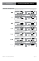
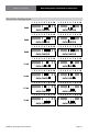
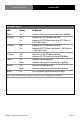
The Fiberlink 3370 Series card units have two dip switch panels with 10 switches. The rst
panel, “DATA CONFIG A”, represents the Ethernet and RS Channel A conguration. The
second panel, “DATA CONFIG B”, represents RS Channel B conguration. Note that all data
channels are available
simultaneously.
DATA CONFIG A
1 2 3 4 5 6 7 8 9
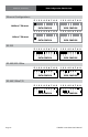
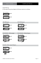
DATA CONFIG B
Data Mode
Baud Rate
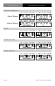
2 Wire/4 Wire Mode
Termination (Input 120 Ohm)
Termination (Output 120 Ohm)
Ethernet
Not Used
Data Mode
Baud Rate
2/4 Wire Mode
Termination (Input 120 Ohm)
Termination (Output 120 Ohm)
1 2 3 4 5 6 7 8 9 10
10