
User`s manual


Page 8 Fiberlink® 3370 Series User’s Manual
Fiberlink® 3370 Series
Installation Instructions
The Fiberlink® 3370 Series of ber optic transmission systems are ready for
immediate use and do not require any special tools or equipment.
The following instructions describe the typical installation procedure:
1) Connect the video source to the video input BNC connector on the transmitter unit.
2) (Optional) Connect your data connections as described in the Data Wiring
section of this manual.
3) Connect the video output cable to the video output BNC connectors on the
receiver unit.
4) (Optional) The ethernet port is congured as an MDI port. If you are not connecting
the 3370 Series to an auto-crossover ethernet port, you may need to use the ethernet
crossover cable supplied with the unit to connect to another MDI port.
5) (Optional) Connect your data connections as described in the Data Wiring
section of this manual.
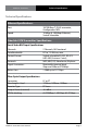
Alarm Switch Settings | Installation Instructions
Alarm Switch Settings for the Transmitter Card
Switch Position Alarm Indication On O
1 Loss of Input Video Enabled Disabled
2 N/A N/A N/A
Alarm Switch Settings for the Receiver Card
Switch Position Alarm Indication On O
1 Loss of Optical Signal Enabled Disabled
2 N/A N/A N/A
Alarm Switch Settings & Options
The Rack Card version of this product has an additional red indicator LED that illuminates
when an alarm condition exists.
The rack card unit also provides an output to drive a model 6020A Alarm Sensing Module
which provides an audible tone and activates a set of contacts for external signaling
purposes.