Communications Specialties’ Fiberlink® 7500 User’s Manual Distribute DVI and stereo audio over one single mode or multimode fiber with no compression, scaling, conversions or frame dropping. The 7500 Series is feature rich, including our unique Triple EDID function and Lock Bandwidth and Equalization capabilities! Fiberlink® 7500, 7510 & 7514 Series DVI and Stereo Audio Transmission over one single mode or multimode fiber.
Fiberlink® 7500 Series Contents Contents Welcome . . . . . . . . . . . . . . . . . . . . . . . . . . . . . . . . . . . . . . . . . . . . . . . . . . . . . . . . . . . . . . . . . . 3 Features. . . . . . . . . . . . . . . . . . . . . . . . . . . . . . . . . . . . . . . . . . . . . . . . . . . . . . . . . . . . . . . . . . . 3 Package Contents. . . . . . . . . . . . . . . . . . . . . . . . . . . . . . . . . . . . . . . . . . . . . . . . . . . . . . . . . .
Fiberlink® 7500 Series Welcome | Features | Package Contents Welcome Thank you for purchasing Communications Specialties, Inc.’s Fiberlink® 7500 Series. The 7500 Series is used to transmit pristine DVI and stereo audio over a single fiber optic core. Compatible with single mode or multimode fiber, the 7500 is ideal for the most demanding of applications, from distance learning to rental and staging.
Fiberlink® 7500 Series Technical Specifications Technical Specifications Model Part Number Specification Unit Type Part Number Single Mode Transmitter Box Single Mode Transmitter Card Single Mode Receiver Box Single Mode Receiver Card Multimode Transmitter Box Multimode Transmitter Card Multimode Receiver Box Multimode Receiver Card Multimode Dual Optical Output Transmitter Box Multimode Dual Optical Output Transmitter Card 7500-B7S, 7510-B7S, 7514-B7S 7500-C7S, 7510-C7S or 7514-C7S 7501-B7S , 7511-B7S
Fiberlink® 7500 Series Technical Specifications Technical Specifications Audio Specifications (cont.) THD+N Channel Phase Differential Crosstalk Input Impedance Output Impedance Audio to Video Diff. Delay (skew) 0.001%, 20 Hz - 20 kHz +0.1º 100 dB (1 kHz) >24 k Ohms < 1 Ohm < 300 uSec Optical Specifications: Operating Wavelength SM CWDM (1300 - 1600 nm band ) MM CWDM (850nm band ) Optical Fibers SM: 8-10/125 microns; MM: 50u or 62.
Installation Instructions Fiberlink® 7500 Series Installation Instructions The Fiberlink® 7500 Series of fiber optic transmission systems are ready for immediate use and do not require any special tools or equipment. However, an Optical Power Meter, such as the Fiberlink® 6615, can be useful in determining optical loss budgets during your systems design and system maintenance. The following instructions describe the typical installation procedure: 1) Power off your computer and the 7500 Series units.
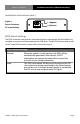
Installation Instructions | EDID Switch Settings Fiberlink® 7500 Series Installation Instructions (cont.) Figure 1: ( - ) Negative Power Connector (+) Positive DC Input Polarity 9-24 Volts AC or DC EDID Switch Settings The EDID Switch has two positions, Internal and Loop, as described in the chart below. For complete instructions on how to operate the 7500 Series’ Triple EDID function, please refer to the “Triple EDID Function” section of this manual on page 8.
Fiberlink® 7500 Series Triple EDID Function Triple EDID Function The Fiberlink® 7500 Series of fiber optic transmission systems come with a unique “Triple EDID” feature set that allows you to capture and store EDID information, acquire EDID information from a connected loop-through display, or allow the7500/7510 or 7502/7512 unit to generate the EDID internally, on-the-fly. The procedure for implementing each are described below.
Triple EDID Function Fiberlink® 7500 Series Triple EDID Function (cont.) Using stored EDID information: Before you can use a stored EDID setting, you must capture and store EDID information as described in the “Capturing and storing EDID information” procedure. 1) Power off your computer and the 7500 Series units. 2) Set the EDID switch to the “Internal” position. 3) Any DVI display can be connected to the loop-through port of the 7500/10/14 or 7502/12/16.
Lock Bandwidth & Input Equalization Fiberlink® 7500 Series Lock Bandwidth and Input Equalization The 7500/7510/7514 and 7502/7512/7516 transmitter units have a Lock Bandwidth (BW) and Input Equalizer (EQ) Setting Dip switches located on the front panel. The default equalizer (EQ) setting is for a short DVI cable, less than 10 feet. The default Bandwidth (BW) setting is NARROW BW. This should work for most clean, “noise-free” DVI sources.
System Connections Fiberlink® 7500 Series System Connections The input and output connections for the Fiberlink 7500 Series are as follows: Audio Connector (Transmitter & Receiver): 3.
Alarm Switch Settings & Options Fiberlink® 7500 Series Alarm Switch Settings & Options The Rack Card version of this product has an additional red indicator LED that illuminates when an alarm condition exists. The rack card unit also provides an output to drive a model 6020 Alarm Sensing Module which provides an audible tone and activates a set of contacts for external signaling purposes.
Indicator LEDs Fiberlink® 7500 Series Indicator LEDs The Fiberlink® 7500 Series has three integral indicator LEDs that are used to monitor the state of the unit. Card versions have an additional Alarm LED. Transmitter LEDs LED Status Definition Power On Indicates that correct power has been applied.
Typical Application Diagrams Fiberlink® 7500 Series Basic Configuration: Loop-through DVI Monitor Two DVI displays with audio Using EDID from Display Single Mode or Multimode Fiber DVI Source 7500/10/14 Tx 7501/11/15 Rx Advanced Configuration: One Projector and One DVI display Loop-through DVI Monitor Multimode Fiber DVI Source 7502/12/16 Tx 7501/11/15 Rx Two DVI displays with audio Using stored EDID captured from Projector Multimode Fiber Note: Both optical outputs of the 7502 Transmitter operat
Fiberlink® 7500 Series Operating Pointers | Troubleshooting Operating Pointers The 7500 Series is available in versions that operate with multimode (MM, 62.5u, 50u) and single mode (SM) optical fibers. Be certain that the correct size fiber is being used for this particular transmitter/receiver combination. Also, remember to check attenuation and bandwidth of the fiber optic cable. The system will only operate properly if these specifications fall within the range of the system’s loss budget.
Fiberlink® 7500 Series Maintenance and Repairs | Certifications Maintenance and Repairs The Fiberlink® 7500 Series has been manufactured using the latest semiconductor devices and techniques that electronic technology has to offer. They have been designed for long, reliable and trouble-free service and are not normally field repairable. Should difficulty be encountered, Communications Specialties maintains a complete service facility to render accurate, timely and reliable service of all products.
Fiberlink® 7500 Series Warranty Communications Specialties, Inc. (CSI) warrants that, for a period of three years after purchase by the Buyer, this product will be free from defects in material and workmanship under normal use and service. A Return Material Authorization (RMA) number must be obtained from CSI before any equipment is returned by the Buyer. All materials must be shipped to CSI at the expense and risk of the Buyer.
Fiberlink® 7500 Series Accessories and Related Products Blue White Broadcast the best results. Black DVI-I Computer Video to 3G/HD/SD-SDI Scan Converter with Genlock Input and Fiber Optic Output The all-digital Scan Do® HD converts DVI input, at resolutions up to 1920 x 1080, to high definition (3G or HD) or standard definition (SD) SDI output, providing broadcast-quality video images.
Fiberlink® 7500 Series Fiberlink® 7500 Series User’s Manual Page 19
Communications Specialties’ Fiberlink® 7500 User’s Manual Fiberlink® 7500, 7510 & 7514 Series DVI and Stereo Audio Transmission over one single mode or multimode fiber. World Headquarters 125 Comac Street Ronkonkoma, New York 11779 USA Tel: (631) 273-0404 Fax: (631) 273-1638 info@commspecial.com commspecial.com ©2013 Communications Specialties, Inc. All Rights Reserved. Scan Do, Fiberlink and the starburst logo are registered trademarks of Communications Specialties, Inc.