Commercial Design Series™ Ceiling Loudspeakers Installation and Operation Manual Model C4LP C4 C6 C6-B C8 Loudspeaker Diameter 4.5” 114.3 mm 4.5” 114.3 mm 6.5” 165.1 mm 6.5” 165.1 mm 8.0” 203.
Introduction Thank you for selecting the Community Commercial Design Series™ of ceiling loudspeakers. Whether you chose them because they deliver exceptionally high quality sound, because they have predictable, uniform coverage so spaces are easy to lay out, because they are easy to install and save time, or because they are very competitively priced for such a high-performance loudspeaker, you can have con idence you made the right choice.
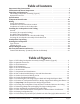
Table of Contents Important Safety Instructions . . . . . . . . . . . . . . . . . . . . . . . L’information de Sûreté Importante . . . . . . . . . . . . . . . . . . . Unpacking and Inspection . . . . . . . . . . . . . . . . . . . . . . . . . Full Ceiling Loudspeaker Assembly (Typical) . . . . . . . . . . . . . . Optional Accessories . . . . . . . . . . . . . . . . . . . . . . . . . . . . . . Speciϐications. . . . . . . . . . . . . . . . . . . . . . . . . . . . . . . . . . Component Identiϐication . . . . .
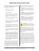
Important Safety Instructions Always follow these basic safety precautions when using or installing Commercial Design loudspeakers and accessories: • Read these instructions. • Keep these instructions. • Heed all warnings. • Follow all instructions, particularly those pertaining to rigging, mounting, hanging and electrical connections. • Do not use this apparatus near water. • Clean only with dry cloth. • Do not block any ventilation openings. Install in accordance with the manufacturer’s instruction.
L’information de Sûreté Importante PRECAUTION: Veuillez toujours suivrent ces mesures de sécurité de base lors de l’utilisation ou lors de l’installation des haut-parleurs Commercial Design et de ces accessoires: • Lisez et Gardez les instructions. • Observez tous les avertissements. • Suivez toutes les instructions, particulierement ceux concernant le calage, support, montage et raccordements électriques. • Ne pas utiliser cet appareil près de l’eau. • Nettoyez seulement avec un tissu sec.
EC STATEMENT OF CONFORMITY This document conϐirms that the range of products of Community Professional Loudspeakers bearing the CE label meets all of the requirements in the EMC directive 89/336/EEC laid down by the Member States Council for adjustment of legal requirements. Furthermore, the products comply with the rules and regulations referring to the electromagnetic compatibility of devices from 30-August-1995.
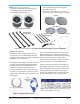
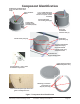
Full Ceiling Loudspeaker Assembly (Typical) (Models: C4LP, C4, C6, C6-B and C8) • Ceiling Loudspeaker Assembly (Qty 2) • Tile Support Bridge Rails (Qty 4) • Bridge Rail Spacers (Qty 4) • • • • Grilles (Qty 2) Cut-out template (can-sized) (Qty 1) Paint Masks (Qty 2) Flat screwdriver (Qty 1) (for screws, connectors and to help remove the grille) Grilles Paint Masks Loudspeakers (with integral back cans) Tile Support Bridge Rails Support Br Bridge Rail Spacers Spac Cut-out Template Flat screwdriver Fig
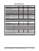
Speciϐications Model C4LP C4 C6/C6-B C8 Ceiling Loudspeaker Type Full Range Coax Full Range Coax Full Range Coax Full Range Coax Description 4.5” Low Pro ile 4.5” Standard 6.5” Standard 8.
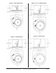
Figure 3. C4LP Dimensions Figure 4. C4 Dimensions Community Commercial Design Series Figure 5. C6/ C6-B Dimensions Figure 6.
Component Identiϐication Combination terminal block cover and cable strain relief clamp Input Terminal Block 3/4” (19 mm) Knockout strain relief on terminal block cover (with conduit installed) Loudspeaker Locking Clamp (shown deployed) Injection-molded Can-Locking Clamp (2) Drop-Stop Installation Assistant Tab (2) Bridge Rail Spacer Bar (x2) Seismic Safety Tab (x2) Drop-Stop Installation Assistant Tab (x2) Injection-Molded Locking Clamp (x2); shown retracted U-Channel Tile Support Bridge Rails Gril
Wiring This manual will serve to assist in wiring and physically mounting Commercial Design Series loudspeakers. The directions include assistance to those installers using a complete Community package of loudspeakers and accessories, including the integral back cans, grilles, tile rails and so forth. We include instructions for use of optional Community Commercial Design Series retro it adapters so that Community Commercial Design Series loudspeakers can be mounted in other manufacturer’s cutouts.
3. Insert appropriate ittings and tighten suf iciently for wire path concealment and strain relief, in accordance with applicable codes. Terminal Block (6” model) 4. You can use lexible or rigid conduit (as required by local electrical codes). Cover/strain relief plate swiveled into closed position and secured to clamp the cable ϐirmly. Note the 3/4 inch (19 mm) knockout in the cover that may be used for conduit.
Installing the Loudspeaker in the Ceiling General Lay out the loudspeaker locations according to the requirements of the speci ic installation and in compliance with applicable safety and building codes. It is beyond the scope of this manual to provide guidance in this area. Community does, however, offer our Forecaster HD Distributed Ceiling System Software to assist you in distributed loudspeaker system design. Please visit the Product Selection area of Community’s website for this software.
designed to drop into the Tile Bridge support rails channels, they will not work properly if mis-aligned. See note and Figures 12 and 13 on the next page. Note: If you’re using loose wires, rather than conduit, ϔirst connect the wires to the terminal block atop the loudspeaker assembly, and secure them with the top cover/strain relief, before installing the can through the cutout and into place. 4. Locate the two Phillips-head actuators around the perimeter of the loudspeaker’s front lange (see Figure 14).
Dry-Wall Ceiling Installation. There are three basic ways to install a Community Commercial Design Series loudspeaker assembly into a drywall ceiling (a.k.a. sheet rock or gypsum board). Some are for new construction, others for retro it to existing construction. We recommend some methods over others and of course the choice is yours. A.
Details for Pre-Installation in a New Drywall Ceiling Inserting the Loudspeaker Assembly into the Drywall Ceiling Optional New Construction Brackets are available for installing loudspeakers in new construction before drywall or plaster is put in place. See Figure 17, and refer to the chart of Figure 2 on page 7 for sizes and model numbers. 1. Bring the wiring from the ceiling to the top of the can and attach it to the terminal block (see the next Section of this manual for details).
Loudspeaker Tap Setting You can use a standard #2 or #3 Phillips or a medium slot-blade screwdriver (not the one provided with the loudspeaker kit), or just press thumb irmly, and twist to adjust the power control dial on the front face of the loudspeaker baf le. As shown in Figure 19, you can make any of ive different settings, although the dial has dual calibrations so at irst glance it appears to have ten settings. The 8-ohm position is the same on both sides and is for a low impedance connection.
Painting the Loudspeaker These loudspeakers’ textured white inish complements most decors and does not require further painting. However, if the interior design requires a custom loudspeaker inish, these loudspeakers are easy to paint. It’s best to paint the baf le before installation. In cases where it needs to be inished along with the ceiling, the loudspeaker baf le can be painted after mounting in the ceiling.
Safety Cabling The Grille Note: Some codes now require that the grille have a safety cable; your local codes may vary. Community makes it easy to comply with an included security cable system, as detailed in Steps 1 through 3 below. 1. Once the loudspeaker is secured in the ceiling, you can attach the safety cable between the grille and loudspeaker. There is a nylon mono ilament loop attached to the grille and looped through a metal clip.
Warranty Information and Service Transferable Warranty “(Limited)” Valid in the USA Only The Commercial Design Ceiling Loudspeaker systems are designed and backed by Community Professional Loudspeakers. For complete warranty information within the USA please refer to the Warranty Card enclosed with the product. Please call 610-876-3400 to locate your nearest Authorized Field Service Station. For Factory Service call 610-876-3400.