
Operating instructions

Community Commercial Design Series Installation and Operation Manual Page 10
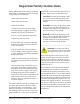
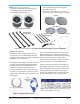
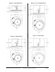
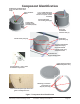
Component Identiϐication
Combination terminal block
cover and cable strain relief
clamp
Input Terminal
Block
Loudspeaker
Locking Clamp
(shown deployed)
Figure 7. Component Part Identiϐication
3/4” (19 mm) Knockout
strain relief on terminal
block cover (with conduit
installed)
Injection-molded
Can-Locking Clamp (2)
Drop-Stop
Installation
Assistant Tab (2)
Low Impedance / 70V & 100V
Transformer Tap Switch
Grille (shown installed
onto loudspeaker face)
Metal safety clip and high-impact
mono ϐilament nylon loops that secure
grille to loudspeaker face
Mounting screw holes
on optional can
adapter/trim ring
U-Channel Tile
Support Bridge Rails
Injection-Molded
Locking Clamp (x2);
shown retracted
Seismic Safety Tab (x2)
Drop-Stop Installation
Assistant Tab (x2)
Bridge Rail
Spacer Bar (x2)
on
t
o
l